A Background-Proof Guide on Communication Systems
Optics, 5G, Wi-Fi, Ethernet, PCIe... all the same.
Irrational Analysis is heavily invested in the semiconductor industry.
Please check the ‘about’ page for a list of active positions.
Positions will change over time and are regularly updated.
Opinions are authors own and do not represent past, present, and/or future employers.
All content published on this newsletter is based on public information and independent research conducted since 2011.
This newsletter is not financial advice, and readers should always do their own research before investing in any security.
Feel free to contact me via email at: irrational_analysis@proton.me
This post is inspired by the excellent SemiAnalysis article on the coming role of optical networks in distributed AI training.
Note: I have some very strong opinions on what multi-datacenter training means. There are some deeper themes…
My goal is to teach all of you (regardless of your background) how communication systems work in a first-principals manner.
“Background-Proof” means the following:
I assume the reader has zero relevant education or experience.
Concepts are explained in-depth. (avoid “dumbing-down”)
Many readers will only understand a small subset of this post, say 20%.
This is perfectly fine!
As long as you learn something new and build a little intuition, I am happy and consider this outcome a win.
If you intuitively understand some key concepts, every communication system will make sense. From 800Gbps electrical Ethernet to Wi-Fi to long-haul optical networks.
It’s all the same.
Note: Your feedback is very important to me. Please leave a comment or privately email me at irrational_analysis@proton.me
Contents:
The real world is analog.
Connecting computers to the real world: ADC and DAC
Fourier Transforms: Time Domain vs Frequency Domain
The Nyquist-Shannon Sampling Theorem
SNR, Bandwidth, and the Shannon-Hartley Capacity Theorem
Impulse Response, Frequency Response, and Transfer Functions
Impedance and Buffer Circuits
Noise
Common Sources
Synchronous vs Asynchronous
Propagation Mediums
Insertion Loss, Return Loss, and Reflections
Calculation and Measurment
Design Choices
Digital tricks to out-smart errors.
Forward Error Correction (FEC) Basics
Example: Reed-Solomon
Reference Signals and Channel Sounding
Modulation
NRZ, PAM, QAM, and all that.
Sending complex numbers… (mixers)
Public Enemy #1: Phase Noise
Public Enemy #2: Non-Linearity
Basic Filter Theory and Terminology
Channel Equalization
FIR/FFE
IIR
DFE
CTLE
Statistical Estimation Theory
Basics
LMS
MLSD
PLL and CDR
Advanced Tactics
MIMO
Beamforming
Multiple Carriers (Multiplexing)
Practical Walkthrough
800Gbps Electrical Ethernet (IEEE 802.3ck)
5G (3GPP Release 15)
Long-Haul Optics (Open ZR+)
Bringing balance to your system.
The Optics Section
Short Reach: DSP, LRO, and LPO
Long Reach: ZR, ZR+, and DWDM
TIA, Drivers, and Optical Modulators
PIC: Electrical —> Things Before Diode —> Diode
Investment Time!
Core Ideas
Broadcom
Marvell
Fabrinet
Ciena
Keysight
SiTime
Lumen
Tower Semi and Global Foundries
Secondary Ideas
Maxlinear
Applied Optoelectronics
MediaTek
Lumentum
Nittobo
Innolight/Eoptolink
Coherent
Cogent Communications
Niche
Cisco/Arista Warning
Astera Labs (┛◉Д◉)┛彡┻━┻
Aeluma
Credo (LRO YOLO)
Existential/Philosophical Nonsense
The Deeper Meaning of Multi-Datacenter Training Clusters
AGI Cultist Rocketship
Corporations are people…
The future is bright.
[1] The real world is analog.
Take a moment to consider the difference in how your biological system (eyes + brain) process light relative to your smartphone imaging system (CMOS image sensor + ISP).
Both systems need an array of sensors to capture light in the form of the three primary colors.
What happens to the sensed data is where things get interesting.
Brains are analog computers. They process data using continuous electrical signals.
Nearly every modern computer is digital. All the data processing is done using discrete, binary values.
Of course, these billions of digital logic transistors are not really binary. It’s still analog but constructed in such a way that the analog world is largely abstracted out.
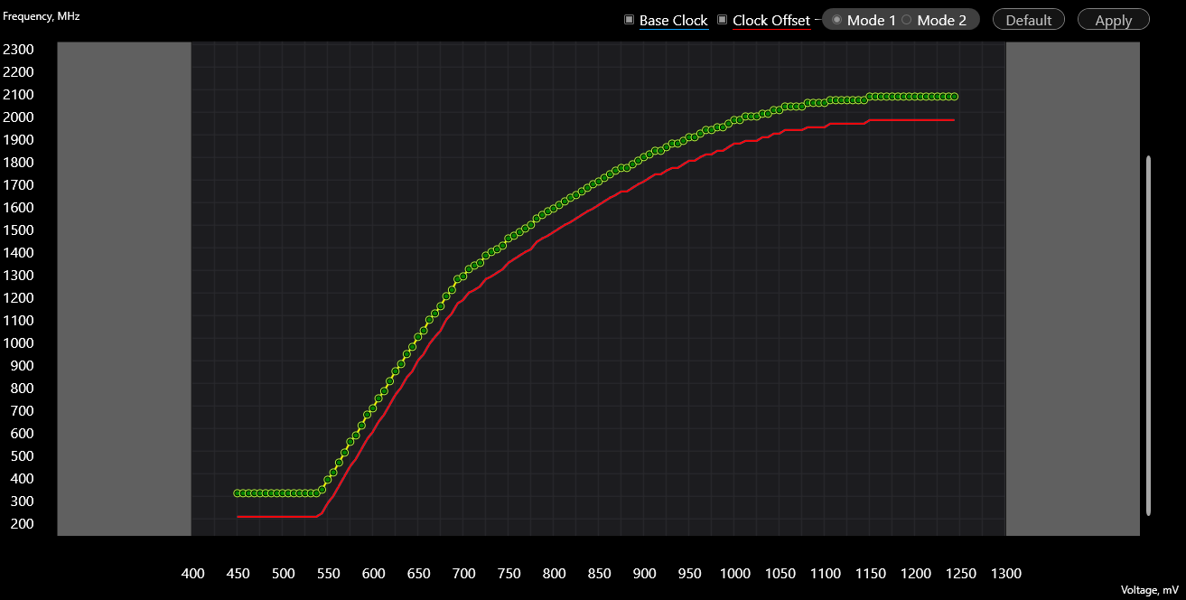
Every digital logic chip has a voltage vs frequency response.
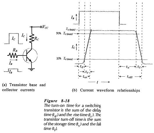
More voltage causes the transistors to switch faster, enabling a higher clock speed of the logic circuit. There are diminishing returns because the process technology the chip design is built upon has intrinsic limits to transistor rise/fall time.
Instability in a digital circuit is a sign that the analog world has re-asserted it’s presence. Bits are flipped because the transistors cannot physically switch fast enough. Internal analog voltages are no longer correctly classified, breaking the binary abstraction.
Processing data in the analog domain is extraordinarily difficult. The modern world runs on digital computers for good reason.
Unfortunately, the real world is still analog. Our computers need to interact with wires, antennas, image sensors, microphones, touchscreens, and keyboard+mouse.
Understanding how this interaction works is key to understanding communication systems, amongst other topics.
Let’s get started.
[1.a] Connecting computers to the real world: ADC and DAC
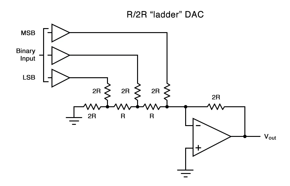
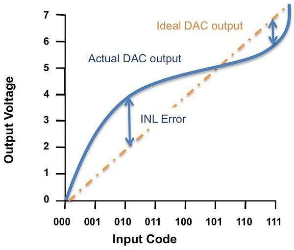
We need a way to convert digital (binary) data into an analog signal. This is called a DAC and here is a simple circuit design.
Three binary signals get combined into one analog output.
For example, 0b000 ties Vout to ground.
0b001 only activates the least-significant bit (LSB) which has the most resistance between it and Vout. Thus, the LSB raises the voltage less than the other two bits.
Non-linearity is a serious issue. Tactics such as differential signaling and interleaving help. It is also common to calibrate DAC bits with a bias voltage.
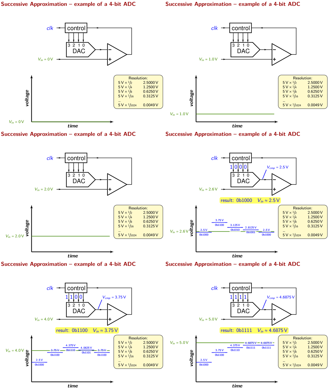
Eventually, transmitted analog signals need to be converted back to digital within the receiver, using an ADC.
The most common type of ADC is the SAR-ADC.
The Wikipedia page is really good. Just click the link and go read that.
For the lazy, I am copying over an excellent GIF and schematic.
Notice how SAR-ADCs have a DAC inside, alongside a non-trivial amount of high-speed digital logic.

Key Points: DAC/ADC
Non-linearity is a problem that needs significant design effort to mitigate.
For high-speed systems, interleaving is a requirement, alongside accurate phase calibration of said interleaves.
Highly sensitive to process node, temperature, and reference voltage. (PVT)
[1.b] Fourier Transforms: Time Domain vs Frequency Domain
This 3blue1brown video is incredible. Go watch it.
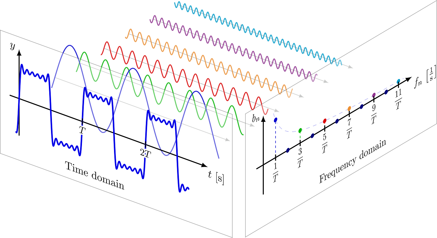
In a nutshell, the Fourier transform allows us to represent any arbitrary time-domain signal as a weighted sum of sinusoids.
Take this square wave built with three sinusoids of varying frequency.
The more sinusoids you have, the better the representation.
Any continuous or sampled time-domain signal can be transformed into frequency domain using a simple change-of-basis called the Fourier Transform.
This is an incredibly powerful tool. Many tasks are easier to accomplish in frequency domain.
Imagine if these three signals were on top of each other, constructively and destructively interfering. You could not separate them out in time-domain.
The Fourier transform would be the same.
Key Points: Fourier Transform
Incredibly powerful tool.
Fast algorithms (FFT) enable real-time Fourier analysis of high-speed signals.
Everything has a frequency domain transform. Images have 2-D transforms. It’s just linear algebra. Highly extendable.
Go watch the 3blue1brown video.
[1.c] The Nyquist-Shannon Sampling Theorem
So we now know how to convert from digital to analog, and vice versa… but how often should the system sample data?
Another way to think about this: How many Fourier Transform coefficients do we need for perfect (or good enough) re-construction.
Too much sampling leads to waste. Excessive die size and power consumption.
Too little sampling results in information loss.
Intuitively, there must be some sweet spot where there is no wasted sampling, and the continuous-time (analog) signal can be perfectly reconstructed from the sampled signal.
This limit exists and is called the Nyquist-Shannon Sampling Theorem.
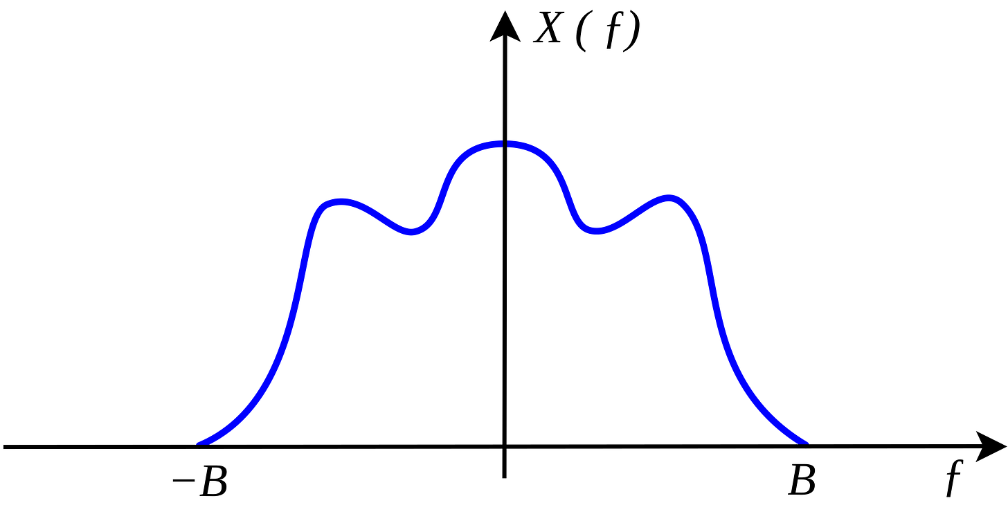
Suppose you have some arbitrary bandlimited signal.
Where the frequencies greater than B are either not present or you don’t care about them.
If you sample at twice the highest frequency of interest, then the original signal can be perfectly re-constructed. Thus, there is no risk of information loss from going back and forth between time and frequency domain.
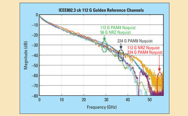
In practice, the Nyquist frequency (half of sampling rate) is very important. Most of the energy will be concentrated at or near the Nyquist Frequency.
More on materials and design considerations in section [3.a].
Key Points: Sampling Theorem
System bandwidth is directly linked to the minimum required sampling rate.
Undersampling results in aliasing, irrecoverable loss/distortion of information.
In practice, most systems over-sample (to varying levels) to improve performance.
[1.d] SNR, Bandwidth, and the Shannon-Hartley Capacity Theorem
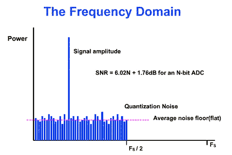
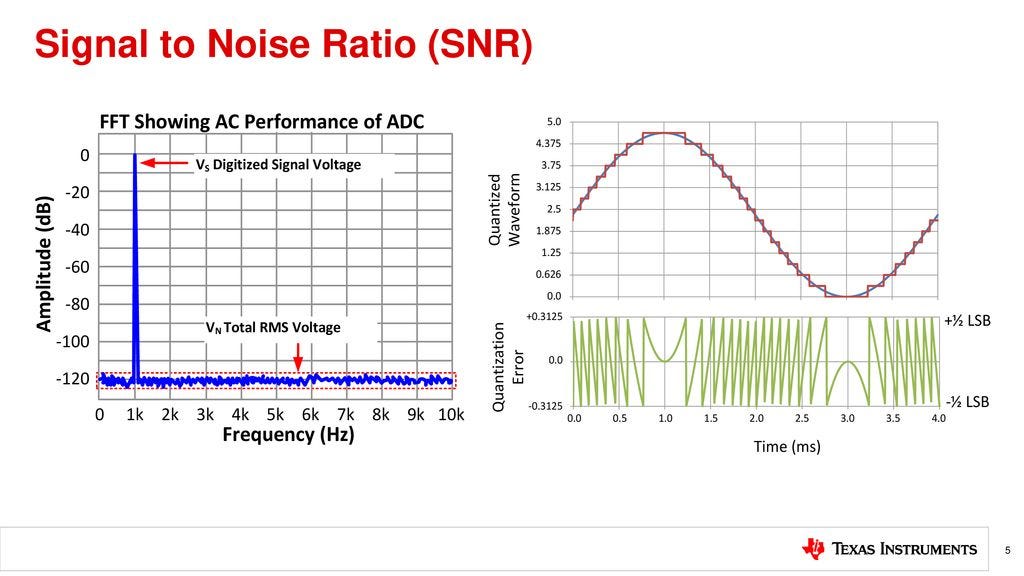
Signal to noise ratio (SNR) is one of two key metrics in a communication system.
Once again, the frequency domain is our friend.
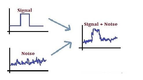
Every system has intrinsic noise, often referred to as the noise floor. More on that in section [2.a].
Interference is also noise from the perspective of a receiver.
SINR includes the power of noise sources that act as jammers. Sometimes, SNR and SINR are used interchangeably. People write SNR even though interference is implicitly included in the calculation.
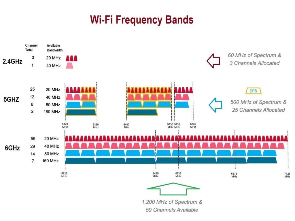
The second key metric of a communication system is the bandwidth. The mathematical concept was already covered in section [1.c] so let’s look at some practical examples.
Wi-Fi operates in unlicensed spectrum. This means that anyone can operate in these frequency bands up to a certain power level, typically 100 mW (20dBm) but up to 1 W (30dBm) in some regions.
Your router scans all the bands and tries to select one with low noise. Every other router nearby acts as a jammer.
Cellular networks operate on licensed spectrum. Government agencies auction spectrum to individual companies for specific uses.
Some of these bands sell for billions of dollars. Bandwidth (spectrum) is a precious resource.
Typically, wireless frequency bands are 100 MHz wide or less due to frequency selective fading and channel coherence concerns.
mmWave 5G is a rare expectation, sometimes operated at 400 MHz wide slices.
Wireline communications (PCIe, Ethernet, NVLink, Infinity Fabric, USB, …) don’t have to worry about spectrum allocation. These systems have multiple GHz worth of bandwidth. More on this in section [3.a].
These two key attributes (SNR, bandwidth) determine the theoretical information capacity of any arbitrary communication system.
Channel capacity is a theoretical limit.
Physics says you can’t go faster than the speed of light.
The Shannon-Hartley Capacity theorem says you cannot transmit more information than “C”.
Note: Don’t think too hard about the units. This is just a theoretical limit. The key takeaway is more bandwidth is (usually) better than more SNR. Drives system design.
In practice, real communication systems are not this efficient.
Notice that SNR scales channel capacity logarithmically while bandwidth offers linear scaling.
Bandwidth is precious.
One final topic is on narrow-band vs wide-band systems. Often, these terms are used incorrectly outside of technical forums.
How narrow does the frequency band need to be?
The answer depends on the propagation medium the system is expected to operate in.
All materials (copper, optical fiber, air, …) have a frequency response.
Here is some arbitrary example propagation medium.
If the system uses a narrow chunk of bandwidth where the loss is relatively flat, say the frequencies between 10 GHz and 11 GHz, then it is narrowband. Using a wider bandwidth where frequency-selective fading is significant results in the system being classified as broadband and requiring different engineering considerations.
How narrow is narrow enough depends heavily on the physical materials. Optical “narrowband” is much wider than RF “narrowband”.
Key Points: Shannon-Hartley Capacity Theorem
Information capacity has a hard limit determined by bandwidth and SNR.
Bandwidth is precious because it scales capacity linearly.
“Narrowband” means that channel coherence is maintained. In other words, frequency-selective fading is negligible. Narrowband/Broadband is frequently mis-classified!
[1.e] Impulse Response, Frequency Response, and Transfer Functions
In order to mathematically model real systems (circuits, communication channels) we need some additional tools.
The first tool is an impulse response, the response of a system to a sharp stimulus.
Imagine a perfect, instantaneous voltage spike. Or a single digital sample of unitary magnitude. The frequency response of the system is labeled as H(z), H(jw), or H(s) depending on the context (discrete, continuous). A lowercase ‘h’ is used for the time domain representation of the same impulse response.
A step response is similar. Input is a unit step function. Zero to one indefinitely.
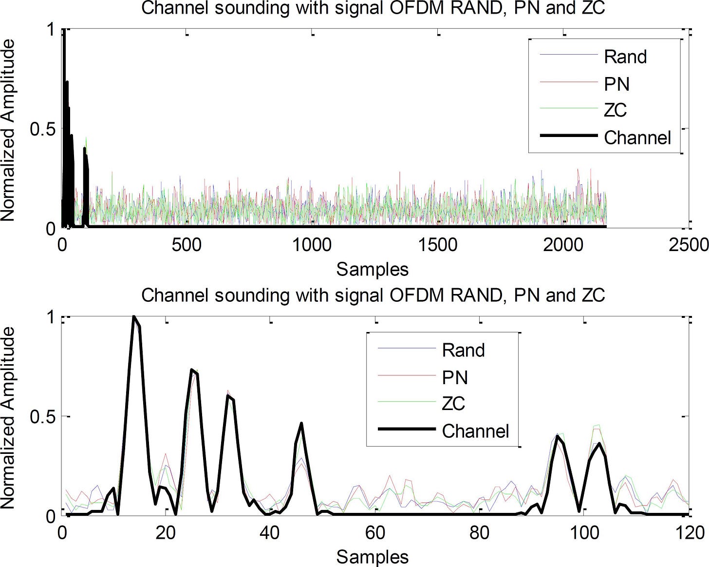
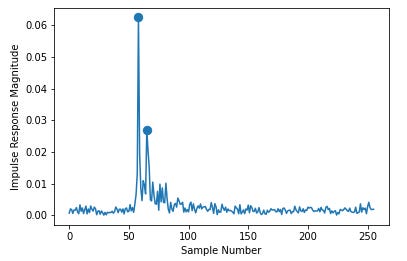
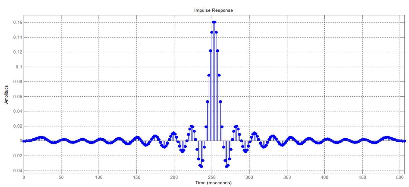
Channel Impulse Responses are very useful. They typically look something like this.
The main spike is a scaled and shifted copy of the transmitted signal. The spikes that follow are reflections, also known as inter-symbol interference.
Broadly speaking, the receiver’s primary objective to is estimate the channel and equalize it. Goal is to use math to “flatten” the channel impulse response into a single, strong, thin spike. This corrects channel distortions.
The frequency response of a system element is very helpful because it can be cascaded with other elements. This is called transfer function analysis.
This math enables lots of fun things. More on that in section [6].
Key Points: Impulse Response and Transfer Functions
Circuits and systems are abstracted into transfer functions using math.
Transfer functions are easy to cascade and analyze.
In the context of a communication system, the idea impulse response is a single scaled and shifted Dirac delta function. Everything else is reflections/noise/junk that needs to be equalized.
[1.f] Impedance and Buffer Circuits
Impedance is important for high-frequency communication systems.
In many instances, it is desirable to have a buffer circuit in between two loads.
An ideal buffer would have unitary gain, a flat frequency response, infinite/zero input impedance, and zero/infinite output impedance.
It’s an impedance converter. Prevents the circuits on each end from interacting with one another via parasitic properties.
Here is a great explanation on voltage follower buffers and why they are needed.
Key Points: Buffer Circuits
Take up area and consume non-trivial power.
Used to isolate circuits.
One end is very high impedance, other end is very low impedance.
[2] Noise
You have heard about “noise floor” and “signal to noise ratio” but these may feel like abstract concepts. Where does noise come from? What factors affect the noise floor of a system?
[2.a] Common Sources
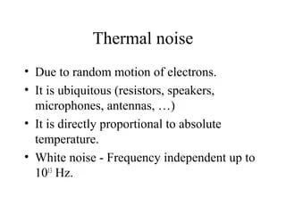
Thermal noise is intrinsic and broadly defined. Semiconductor PDKs have models for the intrinsic (thermal) noise of every device (transistor, standard cell, wire, capacitor, …) in the process node.
Clock time domain noise (jitter) originates from the reference clock (Quartz, SiTime).
Ultra-low noise selenium and rubidium clock sources are used in laboratory environments.
Background noise can come from many sources such as:
Outer Space
Your microwave
Runs at 2.4 GHz, interfering with old Wi-Fi.
Some radiation does leak. (it’s safe, relax Karen)
Other devices on the same frequency.
DC power supply noise.
Neighboring circuits within a chip that are improperly grounded.
Electromagnetic coupling between PCB layers.

[2.b] Synchronous vs Asynchronous
One important distinction I want you to be aware of is that there are two categories of noise.
Synchronous noise is periodic and matched with the clock of a circuit. This type of noise can be mitigated with careful matching of circuit elements. If a particular voltage is 10 mV off, that is ok because all important nodes in the design see the same error simultaneously.
Asynchronous noise is the opposite. Some async noise is random. Often, the two ends of a communication system do not share a common reference clock. Thus, each end will dump async noise in the form of PPM.
A lot of energy is stored in the clock frequency, so some standards such as PCIe require spread-spectrum clocking.
Performance is sacrificed in exchange for lower EM leakage radiation.
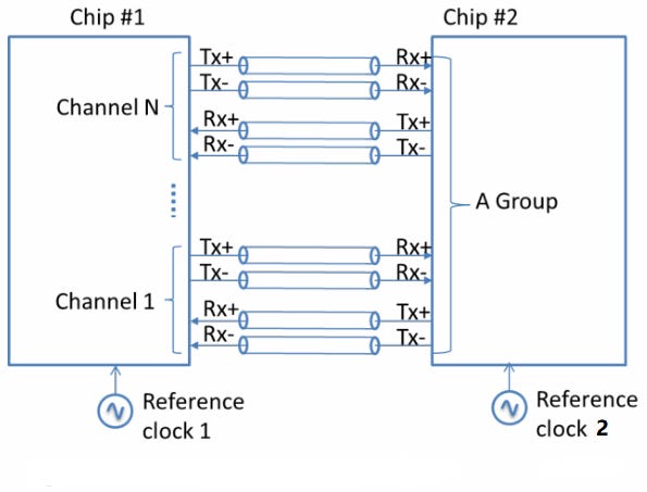
For short-reach communication systems, sharing a clock (known as clock forwarding) eliminates the vast majority of async noise. Automatic 0 PPM. UCIe and NVLink-C2C are both clock-forwarded architectures.

Key Points: Noise
Noise is inevitable, just like death and taxes.
Synchronous noise (with respect to a reference clock) is easier to mitigate than asynchronous noise such as PPM.
Chip-to-Chip technology such as UCIe and NVLink-C2C use clock-forwarding, a special architecture that eliminates PPM.
[3] Propagation Mediums
Every communication system has a channel. Could be an optical fiber, a copper cable, air (line of sight), air+trees+wall (non-line of sight), … whatever.
Math abstracts all this away.
[3.a] Insertion Loss, Return Loss, and Reflections
Insertion loss is the measure of how weak your signal gets. Typically, this number is represented in dB and associated with the Nyquist frequency (broadband) or carrier frequency (narrowband).
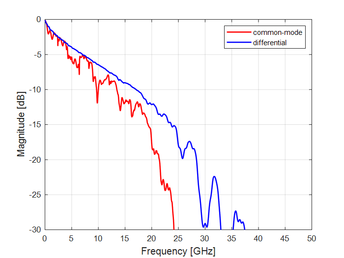
For broadband communications, the linearity of a channel frequency response is very important. Bumps cause problems (reflections).
This is a very important concept. Bandwidth of wireline communication systems is limited by material science. If the frequency is too high, the frequency response becomes shit. Receiver equalizer gets overloaded.
Return loss measures how the signal “bounces”.
Insertion loss (S12) and Return loss (S11) are both scattering parameters, more commonly known as S-Parameters.
This Analog Devices blog is a good overview for beginners.
Key Points: Loss and Reflections
Insertion loss (S12) at Nyquist frequency is the primary driver in how much reach a communication system has.
For wireline systems, the linearity (smoothness) of S12 is important.
Notches and ripple in S-parameters indicate reflections. (bad)
Package, PCB, and connector materials are a non-trivial limitation that drives important design decisions such ad baud rate and modulation scheme.
[3.b] Calculation and Measurment
So how do you measure S-parameters?
There are two primary instruments.
Time-Domain Reflectometers (TDR) send out pulses and measure reflections.
Vector Network Analyzers (VNA) send out frequency-domain pulses (precise sinusoids) to characterize S-Parameters.
Both instruments have their pros and cons. VNA’s are precise but extremely expensive.
Simulating a design is difficult. Every material has its own dielectric constant (DK) and dissipation factor (DF).
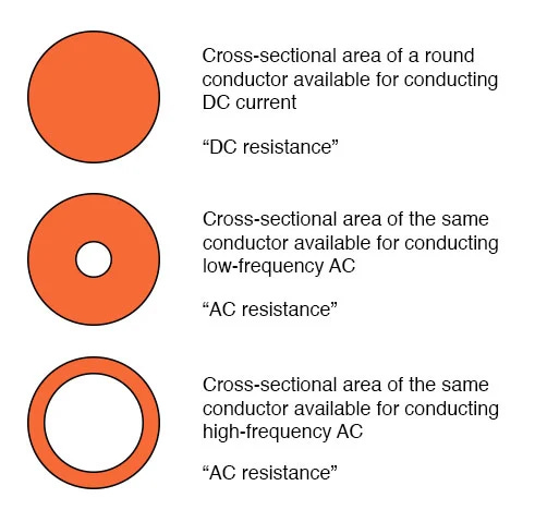
Due to the Skin effect, the thickness of wires drastically change insertion loss. Trace shape and neighboring structures induce parasitic capacitance and inductance, sometimes referred to as electromagnetic coupling.
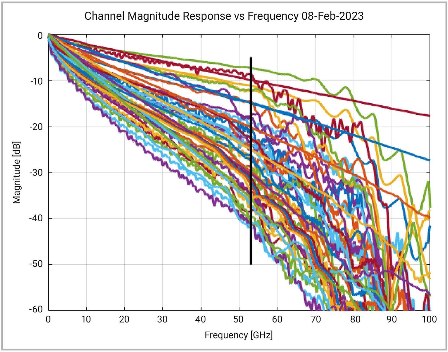
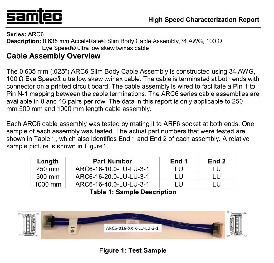
To estimate insertion loss of a wired communication system, you need detailed simulations. Cable length mostly meaningless. Each component (cable, connectors, package, PCB) has its own insertion loss and S-parameters.
Obviously, longer cable probably has more loss. You can’t guess how much by looking at pictures! Loss is measured in dB, not meters.
Guessing wireless channel loss is doable though.
Air at sea level has a well characterized loss. The Friis equation is a fairly reliable tool for estimating wireless channel loss (pathloss).
As you can see, mmWave is 17 dB lower than mid-band 5G. This is a lot for those who lack context.
It gets worse. Friis pathloss estimations assume line-of-sight.
mmWave is easily absorbed by… everything. Walls, your hand, trees….
Key Points: Pathloss Measurment and Estimation
Wireline systems are measured in dB, not length!
You cannot reasonably estimate a cable’s insertion loss from length alone. Skin effect (wire gauge) and connector loss are huge variables.
High-end systems (GB200) have very complex advanced package and PCB designs. Package loss is huge.
Pathloss of wireless channels with line-of-sight can be reasonably estimated with the Friis equation.
mmWave is a commercial failure. Now you understand why.
[3.c] Design Choices
In general, cables tend to have lower loss than PCB materials.
The linearity of component S-parameters is an important consideration in how much bandwidth (baud rate) the system can handle.
You cannot blindly increase transmit power. Amplifiers have non-linearity issues at higher power levels.
Noise from the source circuit and the amplifier itself both scale as you increase transmit power.
Suppose you have a system with 10 dB of gain on each end, Tx and Rx.
A second system with 25 dB of gain on Tx and 0 dB on Rx is not intrinsically better. Depending on many factors, it is probably worse in terms of cost, power efficiency, and performance due to noise figure.
Specifications such as Ethernet and PCIe have limits on transmit power for compatibility and interoperability reasons. Proprietary specs such as NVLink can in theory do whatever they want, but juicing power is not a silver bullet.
In wireless, regulations prevent higher transmit power. Most large cell sites are limited to 45-65 dBm, depending on the frequency band.
dBm means dB with respect to a milliwatt. So a mmWave 5G macro cell at 65 dBm outputs 3000 watts.
[4] Digital tricks to out-smart errors.
Errors are inevitable. There needs to be some digital mechanism to automatically detect and correct errors.
[4.a] Forward Error Correction (FEC) Basics
In a nutshell, FEC algorithms use data redundancy, codewords, and parity checks to detect and correct errors.
A simple (terribly inefficient and fragile) FEC algorithm would be to send three copies of the data and choose the most common result for each bit.
This method triples payload data and still does not provide robustness. Errors are often correlated, which is why most FEC algorithms scramble data and organize it into blocks.
[4.b] Example: Reed-Solomon
A popular FEC algorithm is Reed-Solomon.
RS-FEC has interesting math behind it. If you want to dive into polynomial coefficient codewords and other details, check out this excellent Github blog thing.
Cisco also has a great writeup.
Currently, the most popular wireline FEC is RS (544, 514) which uses 30 parity symbols (00, 10, 01, 11 are the four possibilities of a PAM4 symbol) to form a 544-symbol codeword (data block). The algorithm on the receiver can correct up to 15 errors within the same block.
Therefore, if the physical communication system has less than 15 errors in each block, the upper layer software will not see any errors. No dropped packets. No need to re-transmit.
“Heavier” FEC schemes offer improved error detection and correction at the cost of one or more of the following:
More parity bits/symbols —> reduced coderate (efficiency)
More digital processing, inducing latency.
More die area and power consumption.
RS (544, 514) is a good balance at the moment. Certain companies choose to run lighter, out-of-spec (custom) FEC schemes to save power and reduce latency.
[4.c] Reference Signals and Channel Sounding
Estimating your channel in critical for bringing up the communication link. Channel estimation is a huge topic. Only going over the basics here.
One obvious tactic is to estimate the channel at a lower datarate. But what to send? Perhaps an impulse response?
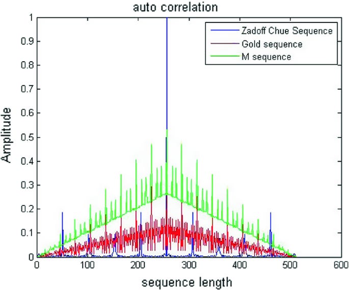
The reference signal needs to have a very sharp autocorrelation to estimate phase delay accurately.
This most popular reference signal is the Zadoff-Chu sequence.

[5] Modulation
Modulation is a topic that a lot of people get confused over.
It is the mapping of binary bits to physical (analog) symbols.
[5.a] NRZ, PAM, QAM, and all that.
Let’s start with the easiest modulation scheme, NRZ.
There are two voltages. One representing ‘0’ and the other representing ‘1’.
PAM<X> extends this to X voltage levels.

We can go further. What if it is possible to transmit complex numbers?
Don’t question this for now. It is explained in the next section.
Now we have two dimensions to play with.
Four binary bits can be transmitted per symbol in QAM16.
Quadrature amplitude modulation is popular in wireless systems, often extending to 256 symbols (8 bits per symbol).
[5.b] Sending complex numbers… (mixers)
To transmit a complex number, you need accurate 90-degree phase shifters on each end of the system.
Interleaving real and imaginary magnitude of each data symbol such that every other sample experiences a 90-degree phase shift allows for the transition of complex numbers.
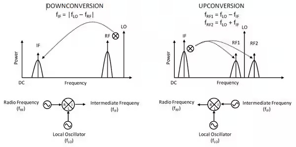
A 90-degree phase shifter is used with a mixer to create a complex (IQ) signal.
Mixers are also used to move signals from baseband (0 Hz) up to the carrier frequency.
[5.c] Public Enemy #1: Phase Noise
Phase noise is a huge problem. QAM modulation schemes are very sensitive to this.
[5.d] Public Enemy #2: Non-Linearity
System linearity is critical for enabling all the DSP tools in the receiver to work as well as possible.
Here is an intuitive reason why linearity is important.
In a highly linear system, the probability of symbol errors is uniform.
A ‘3’ misinterpreted as a ‘2’ has the same probability as a ‘1’ being misinterpreted as a ‘2’.
Nonlinearity means more correlation in errors. Correlated errors (burst errors) are extremely harmful to system performance. The likelihood of too many errors in a single FEC symbol becomes high.
[6] Basic Filter Theory and Terminology
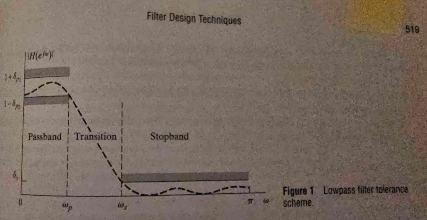
Filters are basically transfer functions that we intentionally add to a system to improve performance.
There are three regions.
Pass band (signal goes through and is optionally amplified)
Transition band
Stopband (signal attenuated by some target value)
There are several important metrics that are commonly used.
3 dB bandwidth determines how wide the passband is.
The passband and stopband will each have their own ripple. Passband ripple means non-linearity. Stopband ripple means that some aggressor bands may be less effectively attenuated.
[7] Channel Equalization
There are several ways of equalizing a channel. Most (basically all) systems use a combination of these methods. Each has its own performance, cost, power, reliability, and area considerations.
[7.a] FIR/FFE
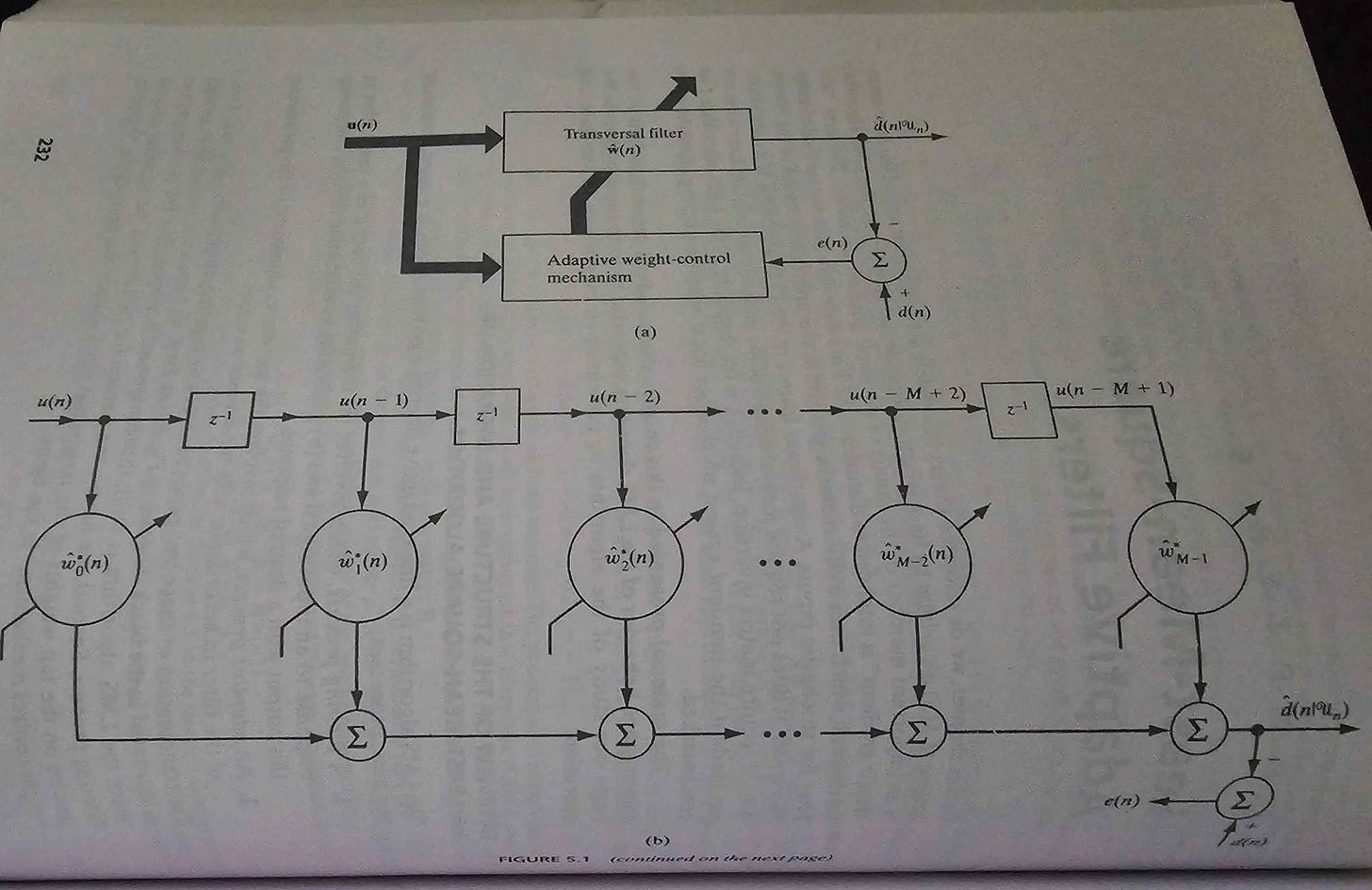
Finite Impulse Response (FIR) filters have two special properties. First, the impulse response is… finite which means convergence is (almost) guaranteed.
In other words, fewer stability issues compared to an IIR filter.
Secondly, filters is the ability to (easily) achieve linear phase.
(very important. explained in next section.)
FIR filters have the following drawbacks:
Need many memory taps to achieve design objectives.
Significant delay/latency.
High area cost.
High power cost.
[7.b] IIR
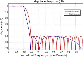
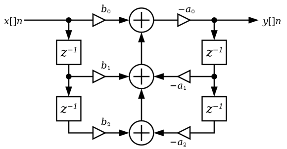
Infinite Impulse Response (IIR) filters look like this.
There are feedback paths, which cause the impulse response to be… infinite.
IIR filters are more likely to be unstable. It takes more design work to deal with this problem.
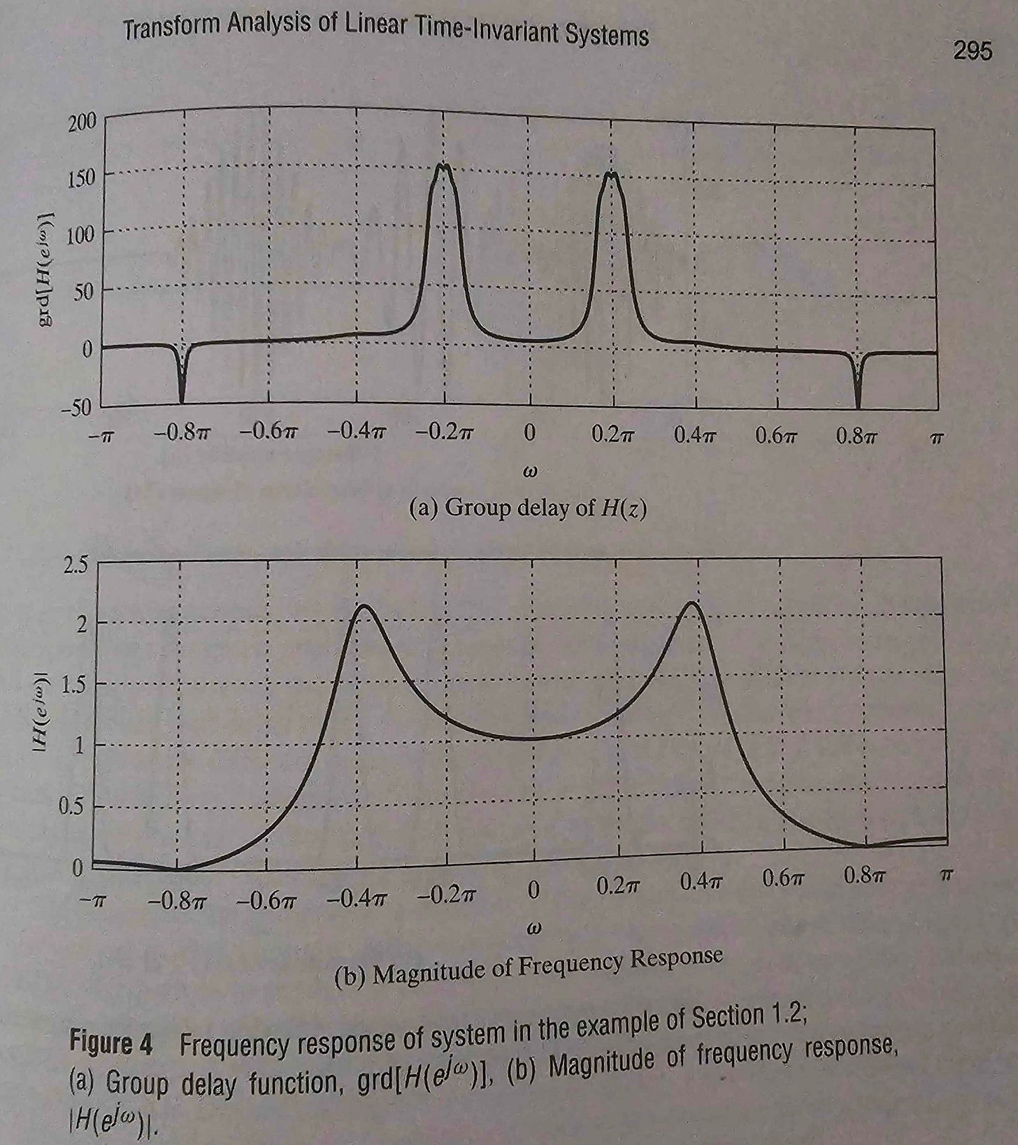
The critical issues with IIR filters is non-linear phase. Here is a great example of what that means.
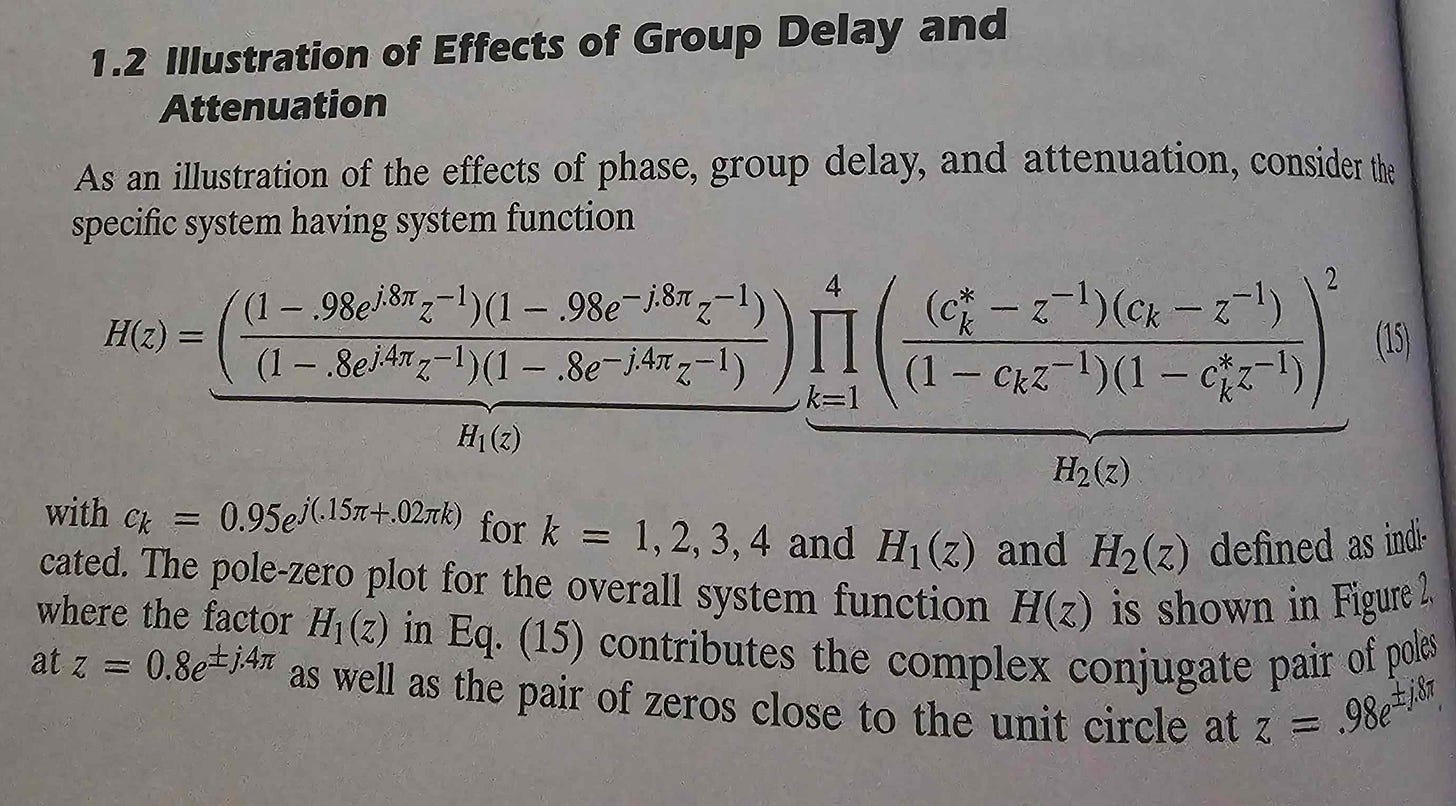
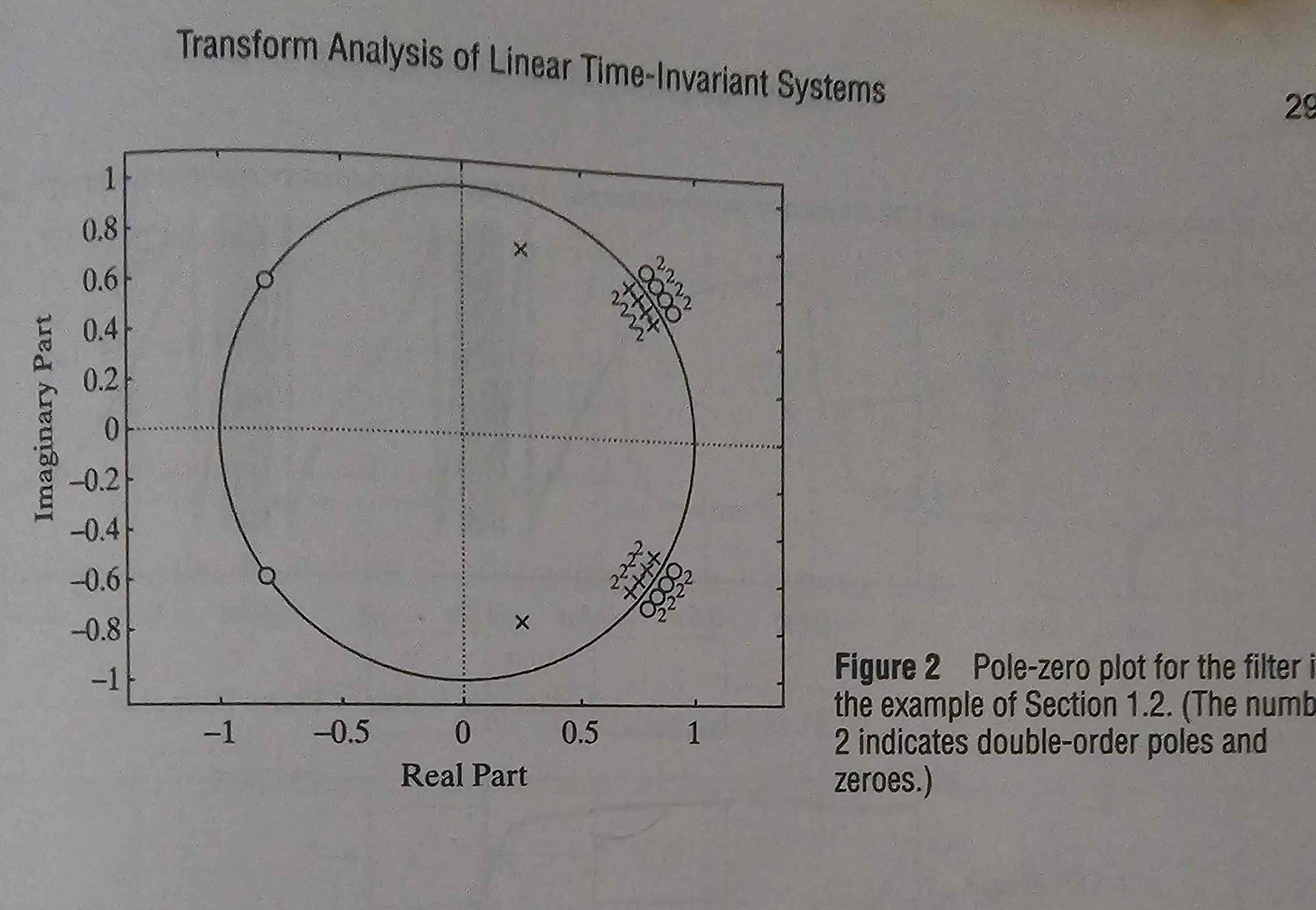
Suppose you have an IIR filter with the following transfer function and pole-zero plot.
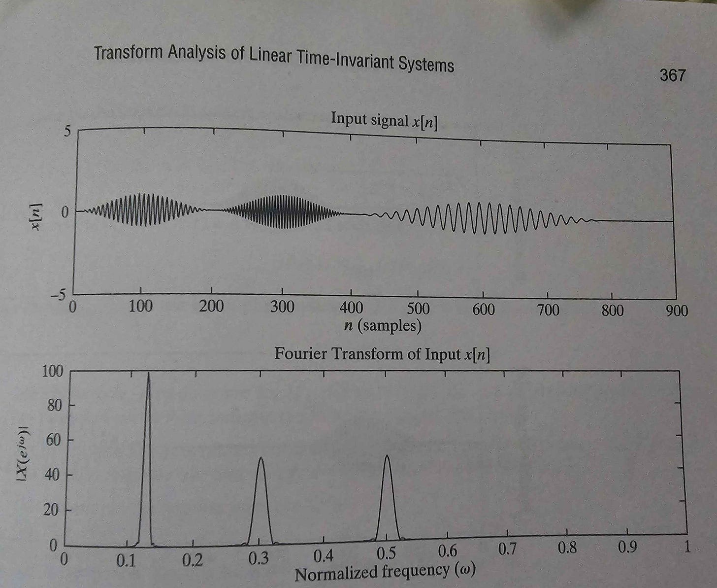
Let’s have an input time series consisting of three sequential sinusoids.
The magnitude and group delay (derived from phase response) of the example IIR filter looks like this:
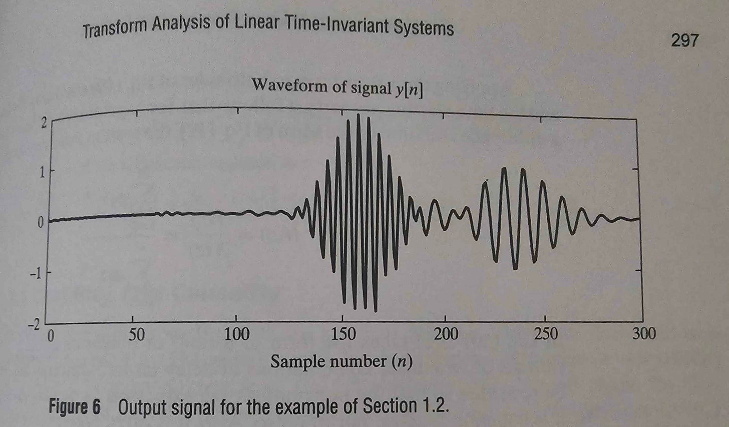
Non-linear phase causes different frequency components to experience different delays. Some applications don’t care about linear phase, but most applications do. IIR filters must be carefully designed to mitigate this issue. Cascading unitary gain IIR filters to correct prior phase shifts is one tactic.
Excluding the two major issues of non-linear phase and stability, IIR filters are objectively better than FIR filters in every way.
Cheaper.
More power efficient.
Sharper frequency response.
More passband gain and rejection band attenuation with far fewer memory taps.
[7.c] DFE
On the surface, Decision Feedback Equalizers (DFE) may look like digital IIR filters.
This is not correct. DFE filters use a slicer that make a hard decision on what value the input should be quantized to. IIR filters do not do this!
DFE filters are non-linear but quite powerful at eliminating reflections, AKA post-cursors.
A major weakness of DFE filters is the timing challenges in high-speed systems.
The benefit relative to a (much larger tap) FIR filter is that DFE taps do not amplify noise.
[7.e] CTLE
Continuous-Time Linear Equalization filters are broadband analog filters.
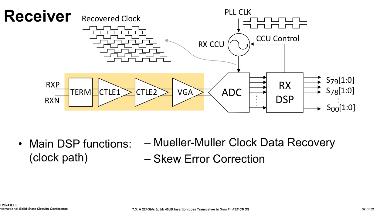
CTLE offers large gain at Nyquist leading to excellent performance, if and only if tuned properly. Designing a 50 GHz wide broadband filter that works across PVT is difficult. Tuning the filter once silicon hits lab is a time-consuming process.
High-speed (224G) designs often have multiple CTLE stages and tuning mechanisms.
Variable capacitance, inductance, and resistance banks can program the CTLE.
[8] Statistical Estimation Theory
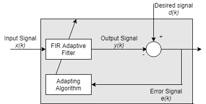
Suppose you already have an equalization filter calculated based on a channel estimate. Re-estimating the channel is expensive. What if you could adapt the filter using a feedback system based on error rate?
[8.a] Basics
Recall that forward-error-correction (FEC) schemes allow the system to know how many errors are in a block and where they are located, to an extent. Thus, the desired signal d(k) can be usually estimated well.
In scenarios which the error rate is high, FEC will be unable to reconstruct the desired signal, and the error signal blows up. The typical response to this is for a higher layer (MAC, PCS/PMA) to ratchet down code-rate, adding more parity bits to the payload. FEC is not the only layer of parity checking. More can be enabled on an as-needed basis.
There are two important families of adaptation algorithms:
Least-Mean Squares (LMS)
Fast, cheap, and simple.
Does not require matrix inversion or correlation functions.
The standard which all other algos are compared against.
Maximum Likelihood Sequence Detection
Uses statistical properties of the sequence to predict the most likely sequence.
Has many variants such as Viterbi, DSFE, and Soft-Output MLSD.
The simplest way of comparing these two is that LMS assumes each symbol is a gaussian while MLSD estimates each symbol’s probability distribution.
[8.b] LMS
Notice how simple the computational load is.
Vector multiply, subtraction, and complex conjugate.
[8.c] MLSD
Viterbi is the most common form of MLSD.
It can be visualized with a Trellis diagram.
Here is a 50-minute lecture that explains this better than I ever could.
Note that a full implementation of Viterbi is quite expensive in terms of power.
There are tricks to reduce the computational load.
[9] PLL and CDR
A phased-locked loop is a simple circuit that tracks an input frequency.
It consists of three major components:
A low-pass filter to remove high-frequency noise.
A voltage-controlled oscillator. (VCO)
A feedback divider can be added to enable programmable output frequencies.
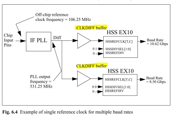
The primary purpose of a PLL is to clean up noise coming from the external reference clock (Quartz, SiTime). All other clocks are derived from the global PLL (GPLL).
SerDes embed the clock into the data stream.
Most modern CDRs are PLL based. This leads to confusion sometimes.
The CDR usually is a PLL, with some modifications. From the perspective of the CDR, the input is a clock with noise in the form of data.
Oversimplified, a CDR is a special PLL with a high-performance phase-detector circuit to compensate for missing clock edges.
I have screenshotted many excellent slides from Professor Sam Palermo of Texas A&M university. If you are interested in learning more, check out his course website:
https://people.engr.tamu.edu/spalermo/ecen720.html
[10] Advanced Tactics
There exist certain advanced (expensive) tactics to boost communication system performance and capacity. These methods are generally cost bound.
[10.a] MIMO
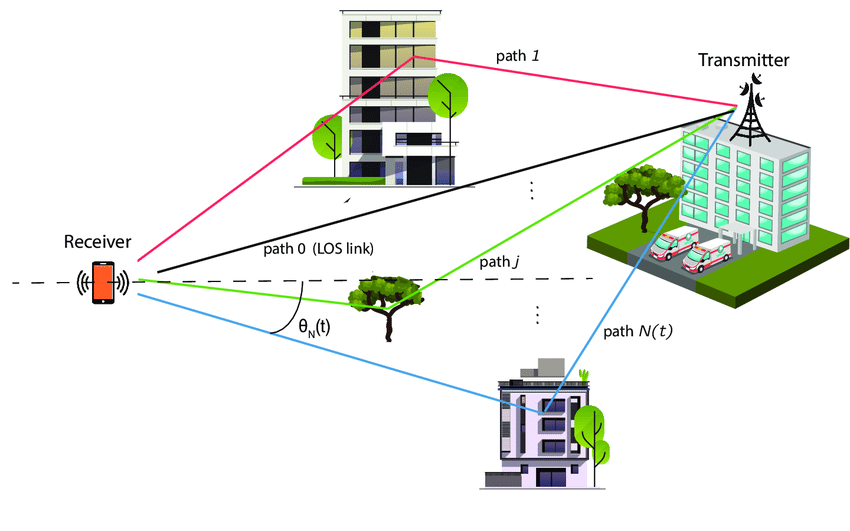
Reflections are usually considered to be undesired interference…
…but what if it was possible to encode different data streams to each signal path?
It is possible, at the cost of system complexity.
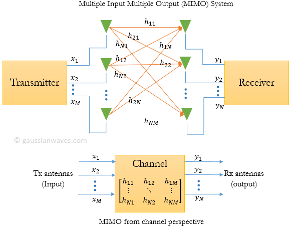
Suppose you have a system where each side has four independent antennas. This system will have a 4x4 spatial correlation matrix.
The rank of this matrix determines how many independent data streams can be encoded onto the multipath channel. Eigenvalue strength indicates how reliable the path is.
It is very common for the primary reflection from the ground to be strong enough to achieve rank2 MIMO operation.
[10.b] Beamforming (Phased Arrays)
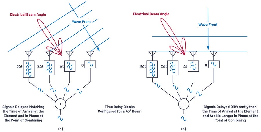
Suppose you have an array of evenly spaced antennas, each of which has independently controllable phase.
The antennas could be place in arbitrary locations within 3D space but that makes things difficult.
Usually, antennas are evenly spaced in a line (Uniform Linear Array) or a 2-D grid (Rectangular array). Circular arrays might sound nice but the math for those involve Bessel function calculus. A nightmare to work with.
Sidenote: The most epic phased array I have ever seen is the SpaceX Starlink dish. They actually used a non-rectangular array geometry!
Intuitively, each digitally steerable (in terms of phase) array element is a FIR filter tap. Phased arrays filter in spatial frequency.
Due to extraordinary costs (CapEx and electricity), phased arrays have largely been limited to military applications.
Each digitally steerable array element needs its own high-speed ADC and DAC.
Hybrid solutions with analog phase shifters exist, sacrificing performance and resolution in favor of reducing cost. Difficult to calibrate.
A lot of compute is needed to process all this data in baseband.
One of the major differences between 4G/LTE and 5G is the extent in which phased arrays are used. 4G/LTE is limited to 8 array elements while large 5G macro cells can reach 64 elements. Larger phased arrays offer more beamforming gain (translates to better SNR) and sharper beams (attenuates aggressor signals from other basestations, phones, noise sources).
[10.c] Multiple Carriers (Multiplexing)
Multiplexing (also known as carrier aggregation) is a method of combining multiple communication channels in the same system.
This method is common in wireless and optical communications as they are both narrowband.
Multiplexing adds significant cost on the analog/RF/optical front-end. High-speed muxes and the necessary analog filters must be carefully designed to ensure neighboring carriers do not interfere with one another.
This cost issue is why Wi-Fi has avoided supporting carrier aggregation for a long time. Wi-Fi 7 is introduces this feature. This is why your home Wi-Fi (almost certainly not v7) has separate 2.4 GHz and 5 GHz networks.
[11] Practical Walkthrough
Let’s go over a practical walkthrough of several communication standards to get a high-level understanding of design tradeoffs. Intuition is key!
[11.a] 400/800Gbps Electrical Ethernet (IEEE 802.3ck)
400GBps Ethernet is built using four lanes of 106Gbps PAM4 SerDes.
The physical module is called “Attachment Unit Interface” or AUI.
There are many specifications for various physical connectors.
800 GbE is built using 8 lanes with a fatter connector.
Electrical specifications are where things get interesting.
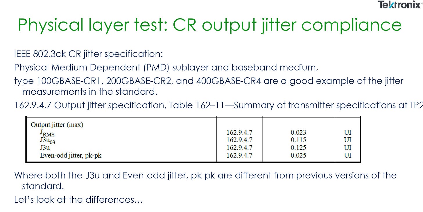
As you can see, maximum voltage (differential pk-pk voltage) is 1200 mV. There is also a minimum diff pk-pk voltage that typically falls around 400 mV. The actual number varies based on the package design and is associated with R_peak and V_f.
RLM is a linearity measurement. (1 means perfect linearity)
Transmitter jitter limits are also defined. This is time-domain noise.
For the receiver, the compliance requirements are simpler to understand.
Receivers must tolerate sinusoidal jitter (pure tone noise) at specified frequencies and magnitudes. This is called JTOL.
Interference tolerance (ITOL) is also required. Think of ITOL as broadband random noise. (full spectrum, not a pure sinusoidal tone)
PCIe differs from Ethernet is several ways:
Requires spread-spectrum clocking.
Much stricter JTOL.
Lower (better/stricter) required pre-FEC bit-error-rate.
Strict latency requirements.
Rigid reach specification. (no sub-specs)

[11.b] 5G (3GPP Release 15)
5G has a very high error tolerance compared to wireline systems. Block-level error under 5% is considered good enough.
Basestations are constantly re-scheduling your Modulation Coding Scheme (MCS) based on channel conditions. This happens on the order of tens of milliseconds. You could go from QAM256 (8 bit per symbol) all the way to QAM4 (2 bit per symbol). Data density (code rate) also dynamically adjusts.
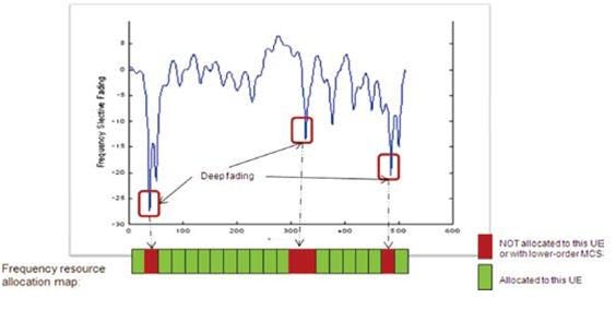
Nearly all modern wireless systems use Orthogonal Frequency-Division Multiplexing (OFDM). This method places thin orthogonal sub-carriers within a frequency band to mitigate frequency-selective fading.
Bad sub-carriers are simply un-allocated by the scheduler.
One major drawback of OFDM is that the signal must be digitally pre-constructed (burns power) and tends to generate high peak-to-average-power ratio (PAPR) time-domain signals.
High PAPR signals place strain on RF components, blowing up cost. Advances in RFFE technology allowed OFDM to become more prominent starting with 4G/LTE. Prior to that, CDMA, SC-FDMA, and TDMA.
[11.c] Long-Haul Optics (Open ZR+)
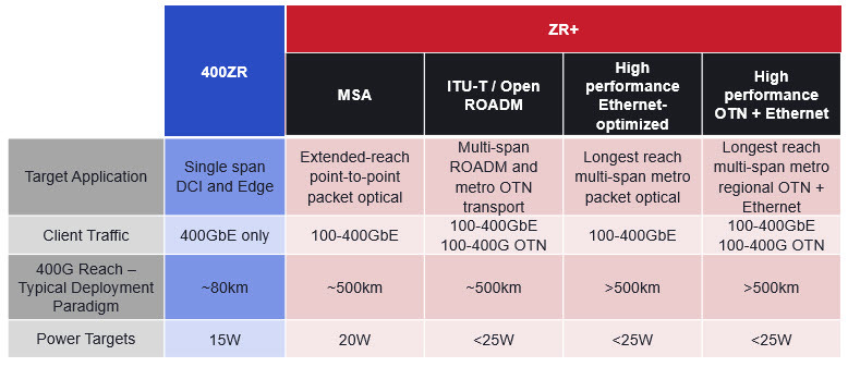
Open ZR+ is a long-haul optical specification. Think about the optical lines that go across buildings instead of within a building.
Very sensitive to PPM. Power also needs to be tightly controlled across temperatures.
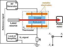
Long-haul optical lasers are so sensitive, they often use piezoelectric heaters/coolers to keep the diode temperature within a tight tolerance.
Pre-FEC BER is very high. This means Open ZR+ prefers to use a very heavy FEC and is tolerant of the latency penalty.
[12] Bringing balance to your system.
Every communication system specification exists for a reason. There must be balance in the context of design objectives and market conditions.
Transmit power is limited by interference concerns, amplifier non-linearity, noise figure of low-level devices, an expected operating temperature.
Bandwidth is limited by regulations (channel coherence too) in wireless, and material quality (PCB, connectors, package, cable, backplane) in wireline.
Modulation method (PAM vs QAM) and order is linked to phase noise and SNR requirements.
Pre-FEC target bit-error-rate and FEC scheme are decided based on latency requirements, re-transmit tolerance, and digital logic power targets.
[13] The Optics Section
Optical systems have some extra vocabulary that I found to be confusing. Some terms like TIA are ambiguous, especially in non-technical contexts. TIA is a fairly simple circuit that many sell-side financial notes treat as some kind of optical-only component.
The last section of this chapter, [13.d], has a mental model I hope you find useful.
[13.a] Short Reach: DSP, LRO, and LPO
oDSP means Optical Digital Signal Processor. Intuitively, it is a SerDes converter.
The host-side SerDes is a normal electrical SerDes.
The line-side SerDes is a special electrical SerDes designed to drive sensitive optical circuits. It is still an electrical SerDes! Optics stuff has not started yet.
oDSP chips are expensive and consume a lot of power. Somewhere in the neighborhood on ~10-15W per module.
LRO and LPO are methods of removing the oDSP, partially or completely.
In LRO, there is still a chip re-timing the transmit waveform. Thus, transmit optics get a clean signal as an input.
LPO removes the oDSP entirely, attempting to drive and receive directly from the photonics IC (PIC). LPO is also sometimes referred to as direct linear drive. Nvidia is rumored to use this in Rubin rack-scale systems.
[13.b] Long Reach: ZR, ZR+, and DWDM
ZR is an old long-haul optical standard that can only reach 80-120 kilometers.
ZR+ is an enhanced version. More modulation options are available, and the power limits are raised.
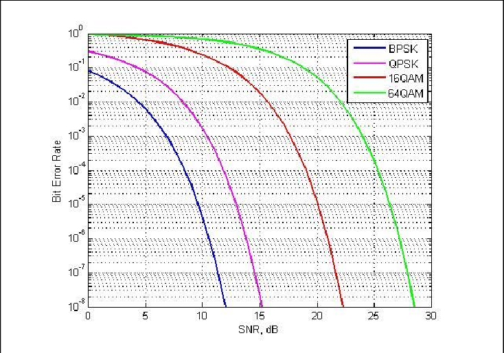
Modulation order and SNR requirements are directly linked.
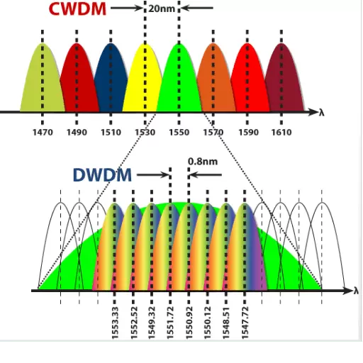
More optical carriers mean more data transmission on the same fiber.
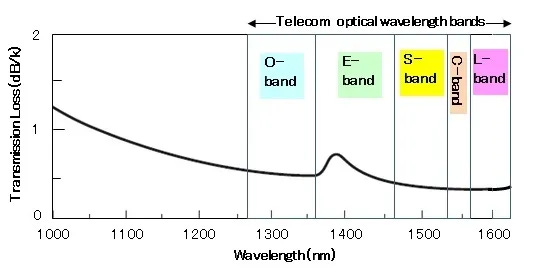
Fiber-optic cables have a frequency response that looks like this:
Plotted against wavelength, not frequency. Easy enough to convert. These bands can be sliced up such that the narrowband assumption holds. (negligible frequency selective fading)
Optical bandwidth is nuts. 100 GHz and maintaining narrowband model. LOL
DWDM requires high-precision optical components, lasers in particular. Expensive gear.
[13.c] TIA, Drivers, and Optical Modulators
TIA stands for Transimpedance amplifier.
It’s just an amplifier that isolates each end and carefully mitigates parasitics. For example, photodiodes have parasitic capacitance that need to be mitigated. TIA’s are common circuits, not some special optical system component.
Optical systems need highly linear gain and noise compensation. This is why TIAs are so popular.
Some good resources:
https://www.ti.com/document-viewer/lit/html/SSZTBC4
https://ultimateelectronicsbook.com/op-amp-transimpedance-amplifier/
https://en.wikipedia.org/wiki/Transimpedance_amplifier
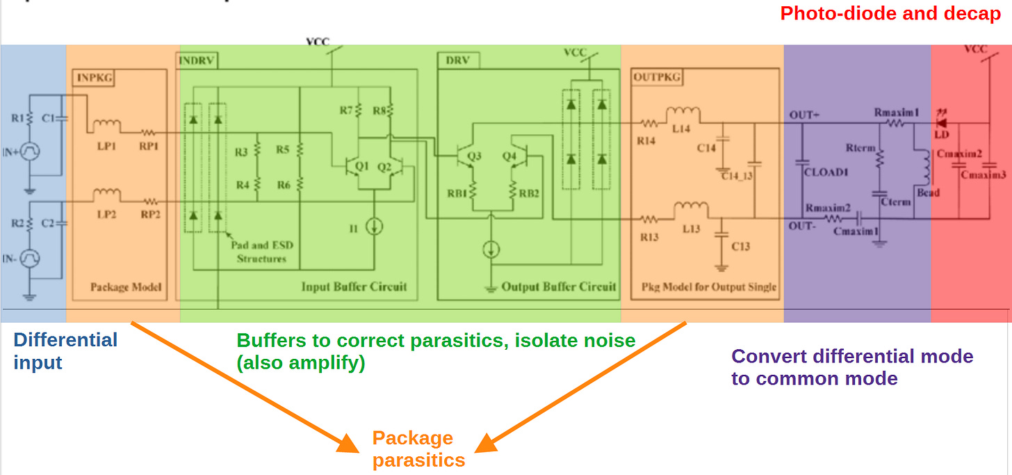
Optical drivers are actually quite simple. It took me forever to find a good diagram to explain this well…
Allow me to simplify….
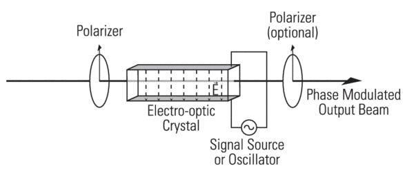
Optical modulation is the tricky part. In a nutshell, the photodiode light output needs to be precisely polarized. Lacking performance will result in symbols interfering with one another. Phase stability is also critical as these systems use QAM modulation.
Remember, phase noise is public enemy #1!
[13.d] PIC: Electrical —> Things Before Diode —> Diode
Optics is a new subject for me. I found the following mental model to be helpful for my own understanding.
On the transmit side:
Normal electrical SerDes goes from device (ASIC, NIC, Switch) to an oDSP chip.
The oDSP chip re-times the signal and outputs a special, ultra-short-reach, calibrated electrical SerDes.
A special driver chip (photonic IC [PIC] built on a special process node) takes in this special SerDes, converts it to common mode (single-ended signal), and powers a very sensitive laser.
The laser outputs light that then passes through a variety of polarizers, lenses, and optical modulators.
These optical components are precise and temperature sensitive.
Use of exotic crystals and materials.
On the receive side:
Optical front-end de-modulation.
A photodiode converts the light into an electrical signal.
A TIA (large die area to ensure excellent linearity) amplifies the signal.
The oDSP converts this calibrated/tuned electrical SerDes into regular standards-based electrical SerDes.
Host chip (ASIC, NIC, Switch) receives the signal.
[14] Investment Time!
I am hyper-bullish optics. The latest generation of high-speed SerDes (224G) is the last generation that can function with active electrical cables.
Loss at Nyquist is too high. Even the most expensive materials are barely good enough. Bump-pitch itself is becoming a major limitation.
There was some debate on if 224G should be at PAM4 (with a doubling of the bandwidth) or PAM6 (only 50% more bandwidth gen-on-gen). It ended up that material science and clever design advances allowed for PAM4 to continue use.
QAM modulation is not really viable for broadband wireline systems due to phase noise (jitter) constraints. 448G cannot be PAM4. The reflections beyond 70-80GHz are too nasty.
Right now, IEEE is debating between PAM6 and PAM8. My guess is PAM8 will be necessary, but we shall see.
Remember, a higher Nyquist frequency means more insertion loss.
Higher modulation order means higher SNR requirements to meet the same pre-FEC bit-error-rate.
448G reach is going to be dramatically worse than 224G. Active electrical cables won’t be enough for most applications.
Optics is the future. Co-packaged optics in particular.
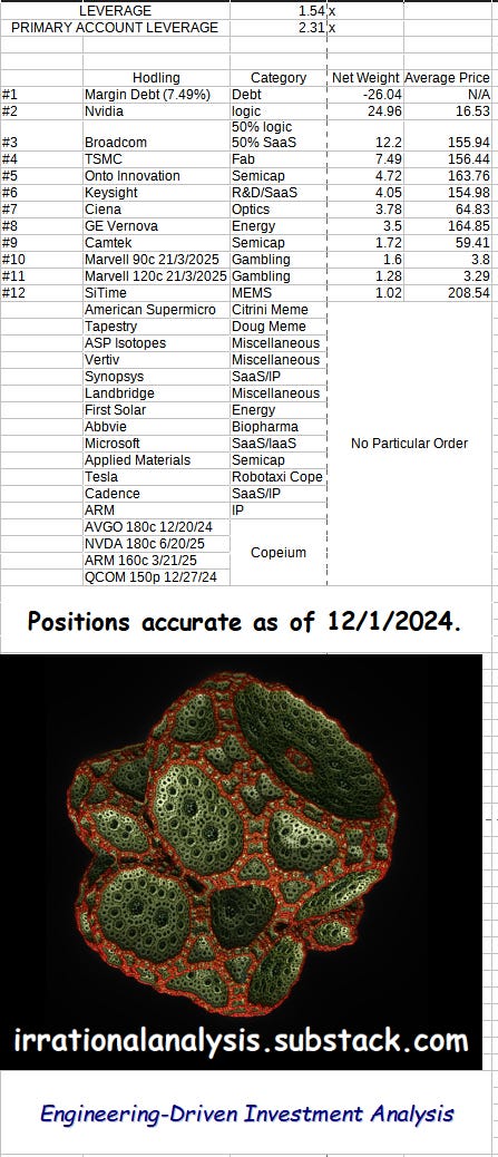
At the time of writing, I hold the following positions.
The following securities will be discussed. I am going to give you a brief overview of each so that you can DO YOUR OWN RESEARCH.
I take ethics very seriously. You know what I own, average price, weight, and my future plans (within reason). Maximum transparency is my self-imposed compliance policy.
I do not make any money from this Substack, consulting/expert calls, sponsorships, or other financial conflicts of interest. This is my hobby. How I choose to invest my own money.
I have a (very fun) dayjob in industry and take great care to keep it separate from what goes on here. Making money on the side is an automatic firing offence. I’m probably going to get fired anyway if/when <employer> finds out… but want to have a chance at talking my way out of the situation.
You know my biases. Go make up your own mind.
[14.a] Core Ideas
Core ideas are stocks that I find genuinely interesting.
[14.a.1] Broadcom
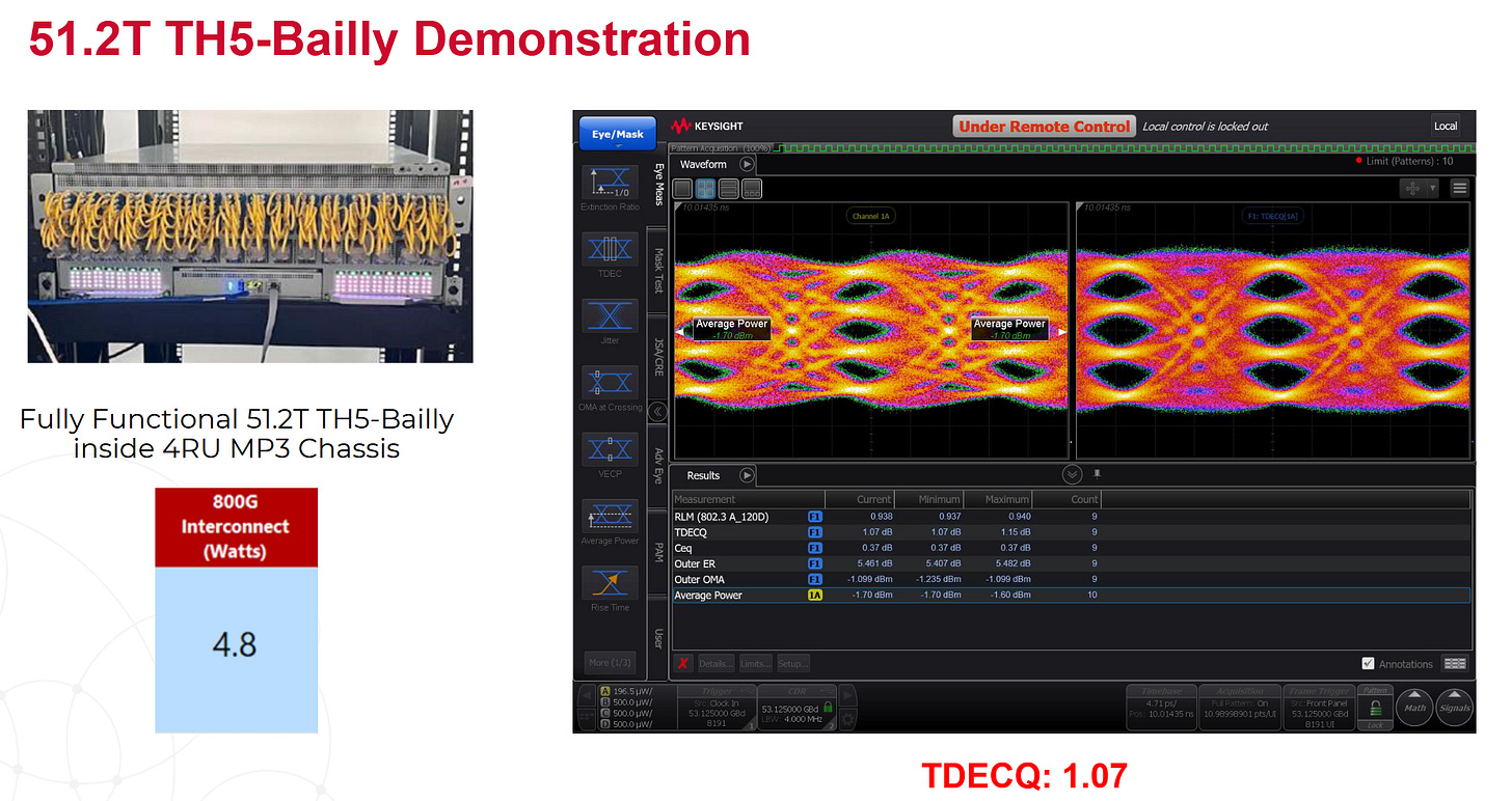
Broadcom covered their incredible co-packaged optics solution in detail at Hot Chips 2024.
The most based marketing guy I ever seen. Maximum confidence. Excellent understanding of technical material.
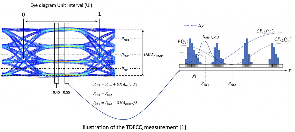
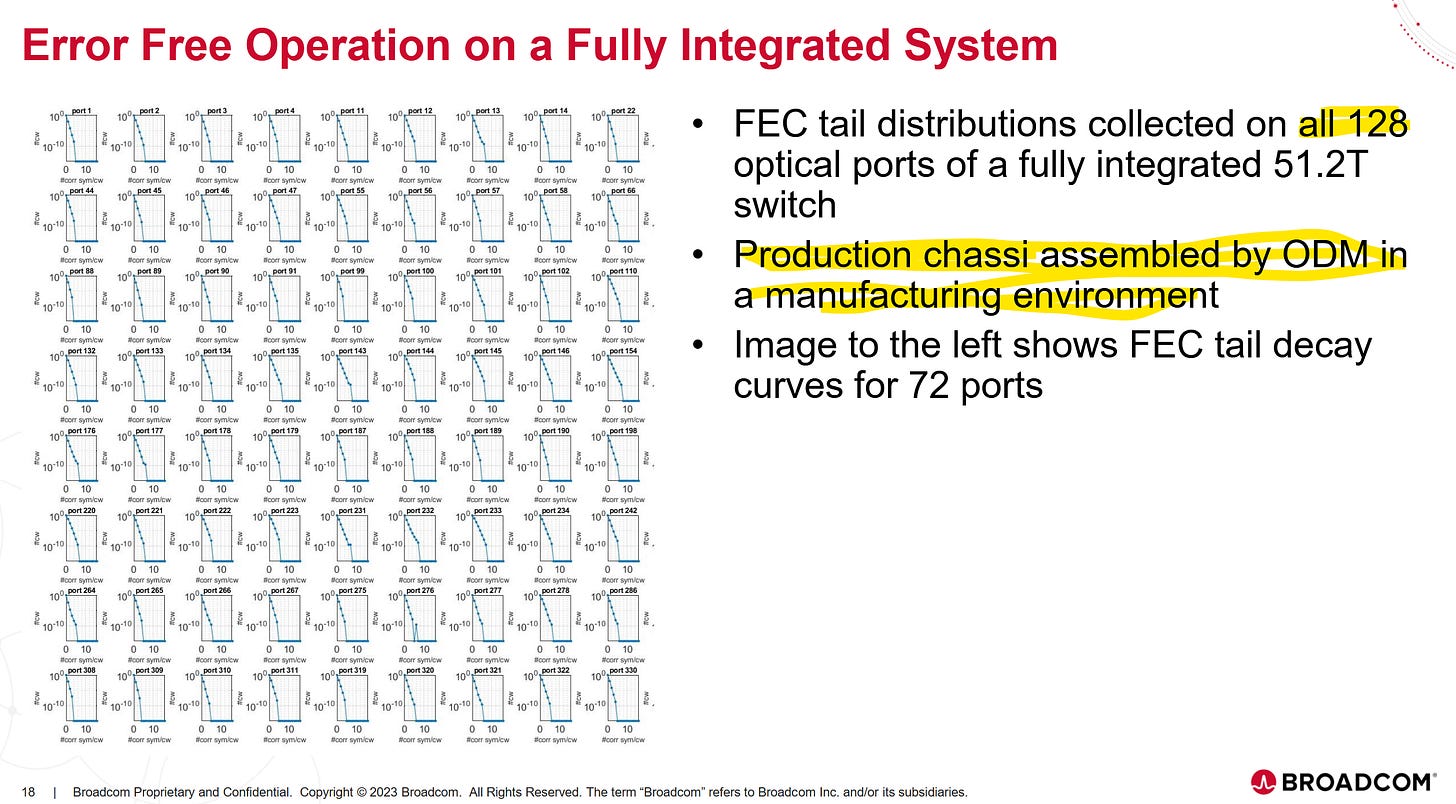
They showed a real system with all ports populated and active. This is to induce maximum synchronous noise.
TDECQ is a measure of eye linearity.
These results are pretty good! Not good enough for commercialization, but not far off from that milestone either.
Recall that the goal of forward-error correction (FEC) is to achieve error-free operation.
They show all the ports using a production quality sample. This is not some hack-ed demo unit built with non-standard (uneconomical) methods.
Broadcom even shows raw FEC symbol data.

Nobody else shares this information publicly.
Customers can easily run a lighter FEC and still achieve error-free operation. Higher effective bitrate and lower latency.
I believe AVGO 0.00%↑ will ramp CPO switches in H2 2025. Q1 2026 at the latest. They are already enabling CPO TPUs for Google.
[14.a.2] Marvell
MRVL 0.00%↑ is a terrible long-term investment. LPO (direct linear drive) and CPO are going to severely harm their oDSP business.
Honestly, Marvell is just an inferior version of Broadcom.
But… the Amazon Trainium 2 ramp is nuts. Great swing-trade opportunity.
Amazon is forcing Anthropic to use Trainium 2. This is round-tripped revenue as far as I am concerned. If the chip was good, Amazon would not need to use financial coercion to gain customers.
[14.a.3] Fabrinet
FN 0.00%↑ is an outsourced manufacturer of optics. They are good at what they do. Low cost (cost plus model) manufacturing that protects customer IP. Dedicated staff and segregated cleanroom space.
Think of this company as the TSMC of optical integration, but with much worse margins.
I have traded in and out of this stock multiple times. The issue is sentiment swings the stock easily. Fabrinet has 100% share of Nvidia 1st-party optical modules. As Nvidia qualifies other vendors modules, people panic and stock tanks.
Long-term, I like this company. CPO is going to drive a ton of business to them. The less sophisticated competitors will not be able to keep up and maintain the level of quality/precision required for CPU.
For now, pods and hedge funds are trading the crap out of this ticker based on Nvidia supply chain whispers. Tread lightly.
Also, most of their manufacturing capacity is in Thailand. Big advantage if Trump follows through on anti-China tariffs.
(I have made a nice profit on each FN trade but not the maximum profit)
[14.a.4] Ciena
CIEN 0.00%↑ is a pure-play for long-haul optics buildout. Semianalysis called them out as a big winner for the multi-datacenter training cluster ramp and I agree.
I was not able to attend the recent OFC in San Jose (despite being local) but a friend did send me pictures from the Ciena booth. They have kickass performance. Really impressive stuff. Sorry but can’t share the pics.
The key concept you need to understand is there is a ton of “dark fiber” out there. Fiber cables that could handle much more data by lighting up more wavelengths but are inactive. The channel (glass cable) supports more capacity! All you need is to add some Ciena gear on each end. AI multi-datacenter training is the demand catalyst Ciena has been waiting for.
Ciena is one of the poster childs of the DotCom bubble. They have been eating shit for all these years. It’s probably a bad omen that CIEN 0.00%↑ is a viable investment idea again.
[14.a.5] Keysight
I have shilled Keysight with dedicated posts multiple times.
It’s almost a quarterly tradition.
This is the most asymmetric risk/reward stock I can think of in semiconductors right now. Let me list out all the positive and negative catalysts/headwinds/tailwinds.
Negative
Wireless might implode further. (extremely unlikely in my opinion)
Positive
Correlated to R&D intensity of AI ASIC development.
As more companies (startups, hyperscalers) try to design their own chips, they have to buy expensive Keysight gear.
For example, you can see Amazon has a high-end 90GHz Keysight UXR real-time oscilloscope for Trainium 2 development.
Cable and connector manufactures (Amphenol and friends) buy high-end Keysight Vector Network Analyzers to characterize individual cables.
Very strong SaaS business. Each Keysight box comes with literally dozens of SaaS upgrades, tools, and features.
Optical proliferation (CPO included) supercharges Keysight’s high-margin revenue growth!
Double the SerDes… line side and host side.
R&D intensity for all the additional components (PIC, TIA, driver, …) and the module itself (package and PCB s-parameter analysis).
Ultra-powerful moat built with superior engineering. A true earned monopoly in high-speed electrical and communication system test equipment.
Is this stock going to the moon? No.
But the risk is very low, and reward is medium. Asymmetric outcome.
[14.a.6] SiTime
Doug (Fabricated Knowledge and now Semianalysis) has a huge overview on SITM 0.00%↑.
This is without a doubt my favorite Fabricated Knowledge piece.
Summary for the lazy:
Every chip needs a timing reference. (refclk)
Traditionally, this is a quartz crystal.
Silicon-based MEMS (SiTime) is a disruptive technology.
Advantages:
Smaller footprint.
Lower power.
Highly programmable.
Disadvantages:
Market inertia (everyone comfortable with quartz).
Terrible jitter performance.
Datasheets that try to fucking gaslight you.

I have read hundreds, if not thousands of datasheets for many components from many vendors. SiTime is the only company that has ever tried to gaslight and manipulate me in the datasheet.
Every CDR has different bandwidth and frequency response. The two pages of assumptions (cheating) SiTime used to manipulate their results are not valid!
It is the customers prerogative to add/model PLL jitter filtering.
If the same (incorrect) methodology was applied to competing quartz crystals, their numbers would be lower too.
This behavior is appalling and inexcusable.
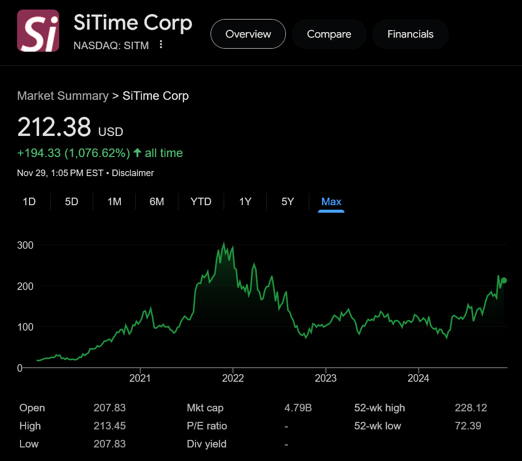
Now let’s take a look at the stock chart to figure out what is going on…
SiTime’s largest customer is Apple. Their own investor materials try to hide how incredibly dependent they are on this one massive customer.
The above stupid rectangle plot would be hilarious if they actually included Apple.
Previously, SiTime was in the iPhone, but they got kicked out due to inert gas issues.
SiTime still is not back in the latest iPhones. A lot of the run-up to the stock is pods and supply-chain whisper degens betting that they made it back in.
Apple is rolling out their own modem next year. iPhones with Apple modem will likely have double the SiTime content, if not more.
The downside to SiTime stock is clear. Large market participants (hedge funds) are wagering that SiTime gets significant Apple revenue acceleration in 2025. Based on conversations with finance-land friends, the consensus is that SITM 0.00%↑ is at fair value assuming Apple revenue ramp.
The upside to SiTime stock is not obvious and super interesting. Nvidia is using them for GB200 NVLink systems. I found this news to be surprising given how dogshit the jitter performance is. But… there is a real engineering reason driving this decision.
Suppose you have a system where the refclk on both ends is SiTime, and thus programmable. If the system is using a proprietary interconnect and protocol, a special “please shift refclk PPM” packet could be sent to ensure 0 effective system PPM.
This is why Nvidia is using SiTime on GB200! I am 99% confident on this.
PPM and jitter both place strain on the receiver. In general, PPM is worse.
In a hypothetical scenario where you have the option to guarantee 0 PPM at the cost of higher refclk jitter, you take that trade every time.
I believe SiTime has an incredible opportunity in datacenter with proprietary electrical links and optical links. Have a small position and opportunistically buying more.
[14.a.7] Lumen
LUMN 0.00%↑ is a steaming pile of debt-laden garbage.
Through a series of unfortunate events, a hilarious quantity of uneconomical, underutilized, dark fiber came into the possession of a single corporation.
The market cap is $8B but it would cost “$150B to re-create” the fiber network. What does that tell you about the economic value and capital structure of this company?
Let’s zoom in on the stock chart.
Hyperscalers are signing large leasing deals to use Lumen’s dark fiber network for multi-datacenter training.
You could be sophisticated and calculate valuation using a complicated financial model that accounts for all the debt, convertible notes, lease terms, blah blah blah.
Or you could just degen trade this garbage like an unhinged monkey.
Embrace your inner primate… 🙈
[14.a.8] Tower Semi and Global Foundries
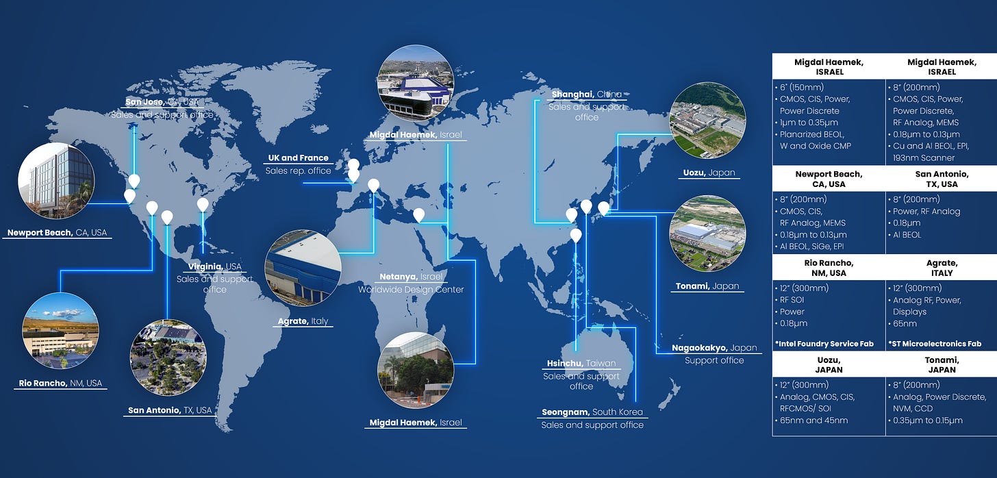
Photonics chips (PIC) need a special process node to work… because physics reasons that I don’t understand.
TSMC is not the leader in this space. In fact, TSMC photonics and RF process nodes are pretty mediocre. Almost nobody uses them.
TSEM 0.00%↑ and GFS 0.00%↑ are the two leaders in specialty photonic process technology. Given how bullish I am on optics, I want to buy shares in one or maybe both but can’t make up my mind.
Here are some quick opinions based on surface-level research. Still looking into this in the background.
Both are protected from tariff concerns which is nice.
And both have 300mm wafer photonics processes. (Tower a bit late)
[14.b] Secondary Ideas
Secondary ideas are mostly here because various subscribers have requested coverage. I’m trying to pre-empt the comments section.
[14.b.1] Maxlinear
If SiTime is the best Fabricated Knowledge post (to date), the MXL 0.00%↑ post might be the most… unfortunate/unlucky.
Reaaaally unfortunate timing.
They made a PAM4 oDSP to compete with Marvell and Broadcom.
It’s supposedly decent. Heard rumors of good power characteristics, despite the Samsung Foundry SF5 process node.
Unfortunately, every other business segment Maxlinear has kinda died.
Rumor is that Intel is the main customer for the MXL oDSPs. Will others choose this product over MRVL 0.00%↑ and AVGO 0.00%↑?
What happens when Nvidia makes their own?
What about ALAB 0.00%↑?
In my opinion, MXL 0.00%↑ has inverted risk/reward. It’s not worth it.
Could be wrong though. I was wrong about ALAB 0.00%↑ …
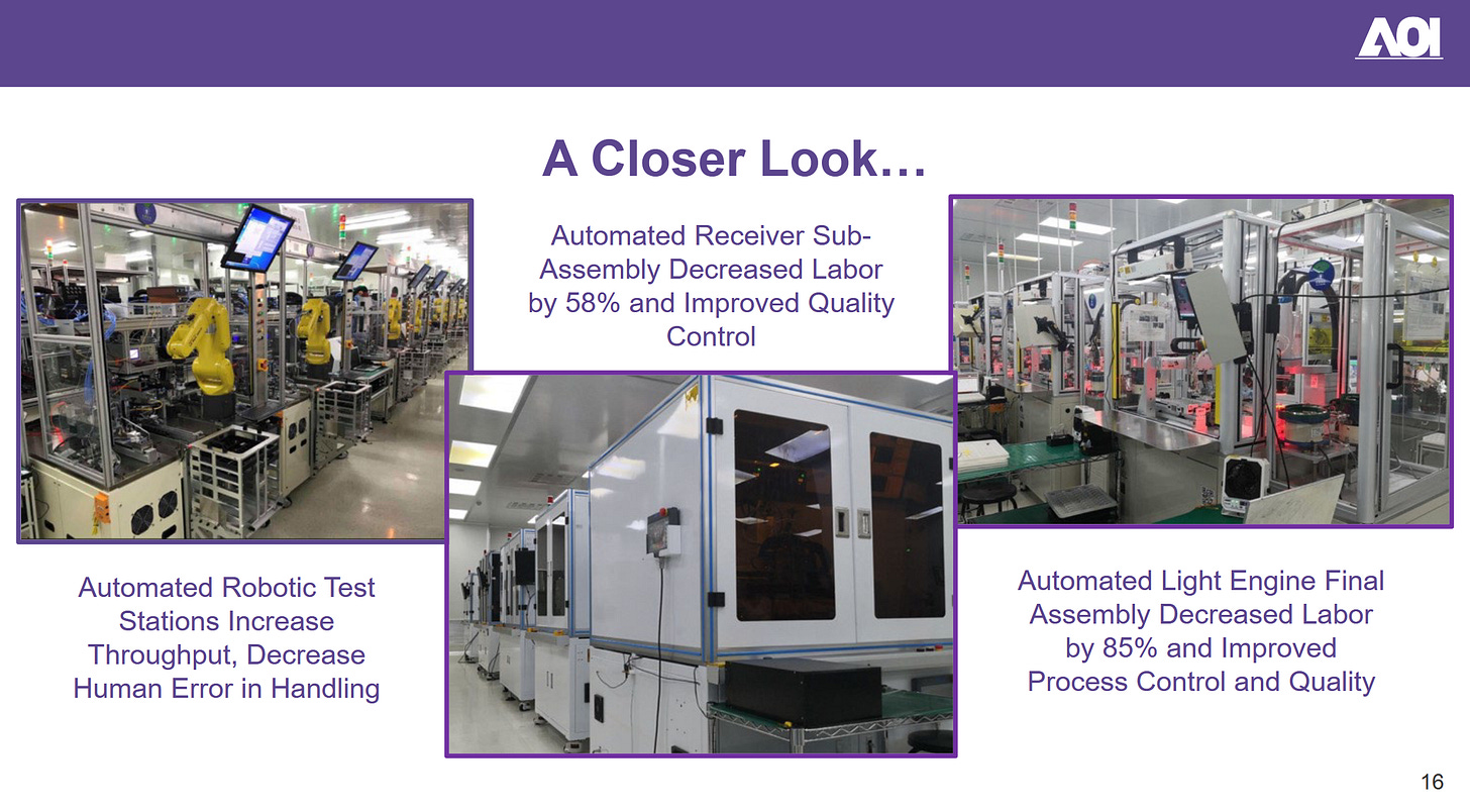
[14.b.2] Applied Optoelectronics
AAOI 0.00%↑ is friends with Microsoft. Strong correlation with that hyperscaler capex.
They also have a patent lawsuit Eoptolink.
Vertically integrated so better margins than a Fabrinet.
And allegedly better performance from custom crystal growth.
(I have no idea how to independently verify this)
Pretty pictures. Nice.
Oh….
The vast majority of employees and manufacturing capacity is in PRC. I guess this is how Eoptolink allegedly stole IP.
This stock is decisively in the “too hard bucket” for me.
[14.b.3] MediaTek
Google is desperately trying to free themselves from the clutches of Broadcom. MediaTek made their own 224G SerDes IP and won a mini-TPU program. It’s real. I have multiple engineering and financial-land sources who have corroborated this info.
Might be a good trade idea.
[14.b.4] Lumentum
So… also vertically integrated like AAOI 0.00%↑?
Yea… they are making similar claims to those of AAOI. Bare-die oDSP co-packaging is interesting. Should save 2-4 dB.
At least the manufacturing is in Thailand (not PRC).
Ehh too hard. Can’t be bothered.
[14.b.5] Nittobo
Nittobo makes high-quality glass fiber with incredibly low dissipation factor.
It is allegedly much better than all the competition.
[14.b.6] Innolight/Eoptolink
Hyperscalers like to bypass the Nvidia+Fabrinet tax and just get optical modules for cheap from these two PRC companies.
Given the impending sanctions from a Trump administration, I don’t think these are good stock ideas but macro and geopolitics is not my speciality.
I still believe that co-packaged optics will be a Fabrinet exclusive growth driver because of the following reasons:
Innolight/Eoptolink lack the sophistication. (until they allegedly/theoretically steal the IP)
Broadcom, Nvidia, and Ayar Labs will want to protect their IP and just pay Fabrinet.
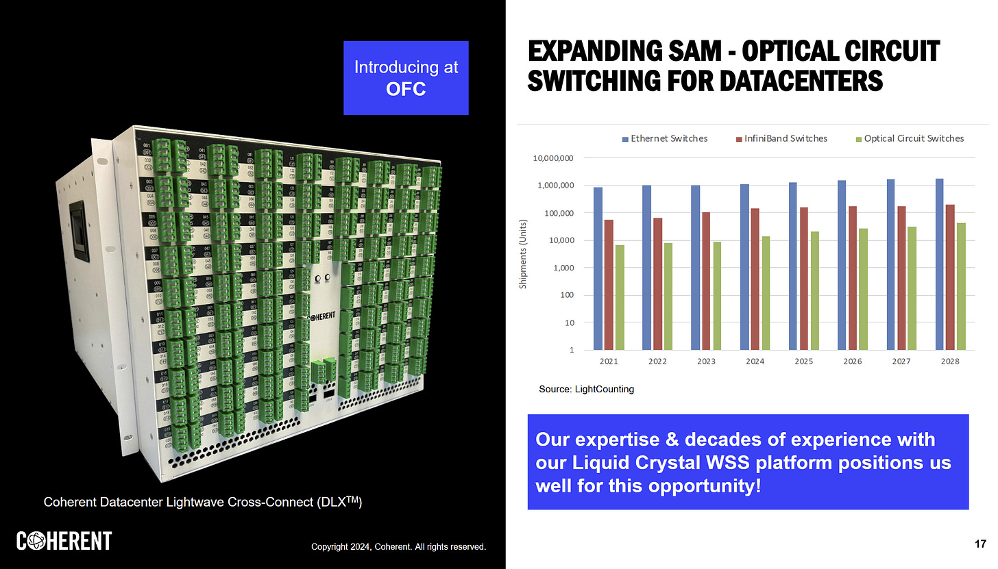
[14.b.7] Coherent
They seem to specialize in phase modulated lasers.
Similar vertical integration claims.
Gross margins are meaningfully better.
Hmm.. they make OCS too. Interesting.
You know what… I like what I’m seeing here.
There is also the (former lamo) Lattice CEO that peaced out to become Coherent CEO.
Maybe they really do have differentiation.
Probably will buy some shares next week.
I might even write a dedicated follow-up post on Coherent.
[14.b.8] Cogent Communications
A boring version of Lumen.
Not worth my time. Moving on.
[14.c] Niche
Miscellaneous stocks you probably should not touch.
[14.c.1] Cisco/Arista Warning
These two are somewhat linked.
Cisco has been pursuing a failed SaaS strategy, neglecting their core business.
Everyone else (Broadcom, Nvidia, Arista, Celestica, Marvell) is running circles around Cisco in the core switching and routing markets. No AI boom for you!
One of the financial friends I talk to (let’s call him Mr. Book Value) brought up that CSCO 0.00%↑ is super cheap and even has a mini Ciena inside it.

I still don’t think that makes Cisco a worthwhile investment. Too much garbage and clueless management to justify dumpster diving.
Arista does not make their own silicon. They buy Broadcom chips and build a switch and software platform around them.
Every quarter, they have this slide updated.
Cisco is a no from me dawg.
But so is ANET 0.00%↑.
I cannot think of a reason why anyone would buy ANET 0.00%↑ instead of AVGO 0.00%↑. Broadcom is more diversified, makes the important silicon, and has co-packaged optics IP. CPO can’t be good for Arista. Probably content loss?
Also, what prevents hyperscalers from buying white-box (semi-custom) switches from CLS 0.00%↑ that are powered by Broadcom silicon?
Arista Networks is in a weird no-mans-land. Does not make sense to invest. Better options out there IMO.
[14.c.2] Astera Labs (┛◉Д◉)┛彡┻━┻
I have covered ALAB 0.00%↑ multiple times and stand by that coverage despite getting crushed on my massive short position that went kaboom.
Still think this is a retarded bubble stock. I want to re-short in the same way bugs are attracted to zappers.
I do want to highlight AYZ of Global Technology Research.
There are several important pieces of information in the above post that would have dramatically altered my investment thesis. I am now a paid sub to AYZ/GTR on my primary Substack account. Check him out.
[14.c.3] Aeluma
This is a stock traded on OTC (over the counter) markets.
One of the nice things about running a newsletter is I get to meet new people and learn about things I never would have encountered otherwise.
Someone has brought Aeluma to my attention multiple times. By default, I have a strong prejudice against OTC listed companies. The probability of fraud is much higher than a regular exchanged listed company.
With that said, I have watched the Aeluma CEO present several times and this dude seems legit. Good vibes.
They guy likes to highlight multiple possible end-markets for Aeluma technology. He seems to be throwing possibilities at the wall and waiting for one to stick.
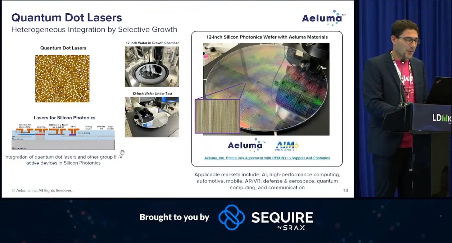
This is what got my attention.
Aeluma claims to be working on the holy grail of silicon photonics. No hybrid bonding. No advanced packaging. Literally print the photonics stuff directly onto a pre-fabricated silicon wafer.
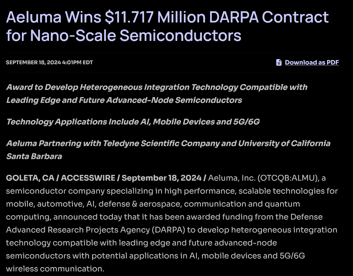
They have a DoD grant to work on this technology.
Which makes sense. Traditional photonic integration technology induces a lot of noise and loss. Military is willing to pay a large premium for lower noise floor.
The UC Sanda Barbara colab has resulted in a paper that I found interesting.
(Aeluma CEO is a professor there)
If they can successfully and heterogeneously add InGaAs layers to a normal CMOS wafer, they will have achieved the holy grail of co-packaged optics.
No package!
Directly printing of photonic elements (laser, photodiodes, modulators) on a regular CMOS silicon wafer.
[14.c.4] Credo (LRO YOLO)
Credo has a LRO DSP with no customers. The stock seems to be a pod-boi meme of people gambling that this Dove DSP gets a customer.
It was released a year ago and still nobody has bit.
You may be thinking…. what prevents Marvell/Broadcom from tapeing out half of their existing oDSP solution and marketing it for LRO?
Nothing.
Still, it is possible a hyperscaler qualifies Credo active LRO cables for a project which leads to a revenue spike.
Interesting gambling/trading idea.
[15] Existential/Philosophical Nonsense
The engineering/educational and financial/investment content is mostly over. I hope you learned something new.
The rest of this post is going a bit off the rails. Philosophy, existential dread, and some of my core beliefs.
I have re-written this material several times. Maybe it is coherent (pun intended). Don’t care anymore. It’s time to publish and move on to other projects.
Note: Next post is on Tenstorrent and the state of AI hardware startups. It’s going to be great. Subscribe! Feed narcissism.
[15.a] The Deeper Meaning of Multi-Datacenter Training Clusters
Multi-Datacenter training AI clusters are supercomputers.
Distributed supercomputers.
This is a terrible idea. Throughout history, supercomputers have been co-located to avoid NUMA (non-uniform memory access), latency, and programming model challenges.
This is a terrible idea. Everyone is going for it anyway.
What is happening right now flies in the face of decades of supercomputer history and theory.
The efficiency will be terrible.
I have read every single Semianalysis piece. The multi-datacenter training post was informative and interesting, as usual.
But it also legitimately terrifying.
It’s not just some industry development.
Oh look, people are developing innovative fault tolerance and all-reduce methodologies…
No no no.
This is a signal.
A signal that the AGI cultists (backed by corporate masters) have gone all in.
[15.b] AGI Cultist Rocketship
I am convinced that a cult has developed in the San Fransico Bay Area. The population here is already brain damaged; multiple sigmas removed from normal.
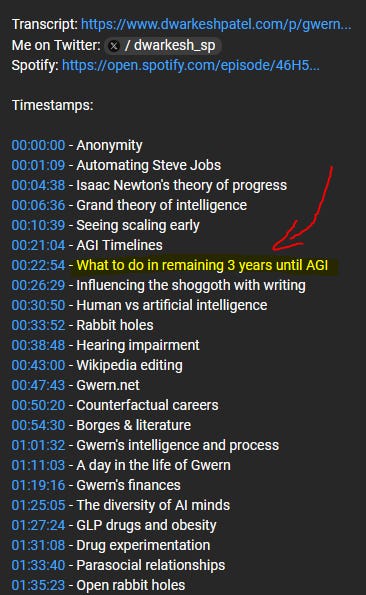
Ignore the acronym “AGI” for a moment. The above Tweet seems a little cult-ish… right?
Why yes. What a reasonable interview question. What will you do in the next three years, waiting for the machine god to come?
Many investors are concerned about silly things like “revenue”, and “ROI”. AGI cult does not care about such artificial constructs.
The name of OpenAI’s CUDA replacement is Triton, named after the planet Neptune’s largest moon.
This is no coincidence. We are indeed going to a moon, but not the lame rock that orbits our pathetic planet.
AGI cult is building a rocketship.
Maybe the rocket explodes. Maybe it arrives at Triton, but the OKLO 0.00%↑ nuclear reactor fails, resulting in everyone on board freezing to death on the lunar surface.
The rocket is under construction. From an investment perspective, this epic bubble (I really hope it’s a bubble…) is the opportunity of a lifetime.
Attempting to attach financial metrics to this rocket is foolish. It’s like trying to psychoanalyze a cult.
Get in or forever wonder what could have been.
Let’s move on from the AGI cult itself. They don’t really matter in a way. All of this crazy shit is happening because the cult has wealthy financial backers. Follow the money.
What are the hyperscaler’s plans? Why have the mega corps funded this cult?
[15.c] Corporations are people…
As a failed United States presidential candidate, one said:
Corporations are people my friend.
For those who are not aware, the United States Supreme Court ruled in Citizens United v. FEC that corporations are to be considered people for the purposes of campaign finance law.
I quite like this framework. Corporations **do** behave like individual people in a way.
Every corporation is an amalgamation of employees, biased towards those who have tenure. There is a natural selection that implicitly occurs. Some people stay at a company for 10, 20, even 30 years and become deeply engrained with the company culture. Others leave after 1-2 years.
Politics are also a major force within corporations. Just like how an individual city, state, or country have political views, so do corporations.
But what exactly is a corporation? Have you ever asked yourself this question?
Corporations are artificial constructs, created to distribute profits and liability/risk.
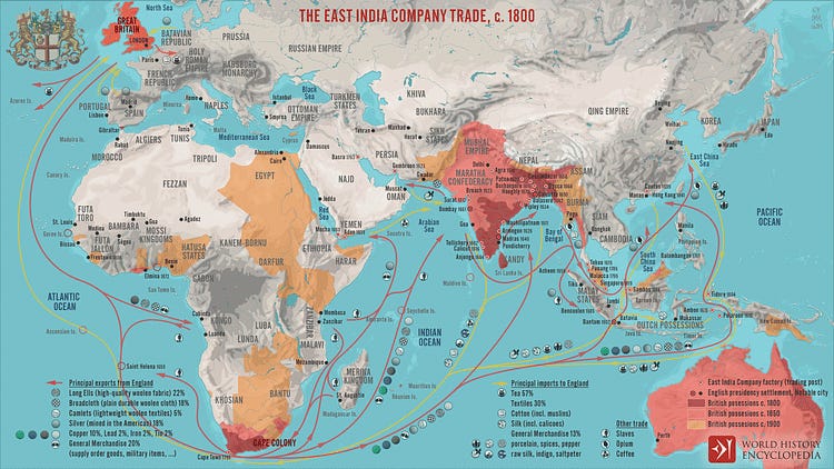
One of the most famous early corporations is the East India Company.
Suppose you invest in a single trading ship. There is a real possibility the ship sinks and never returns. Thus, it makes sense to form a corporation that controls many ships and distributes both risk and profits to the shareholders.
Corporations have what is known as a fiduciary duty to investors.
In short, C-level executives (CEO, CFO) are legally obligated to act in the best interest of shareholders at all times.
Corporations track expenses in two broad categories:
Operating Expenses (OpEx)
Capital Expenditures (CapEx).
You are OpEx. Take you base salary and multiply it by 1.25-1.4x to account for benefits to proximate your annual OpEx cost. This is an HR rule-of-thumb. Often, financial value of benefits delivered to an employee are more than the cost due to tax breaks.
Are you really worth all that money? How many years until a semi-competent AI agent replaces you?
AI agents don’t sleep. They do not ask for time off. They work 24/7/365. They can rapidly communicate with other AI agents.
AI is a massive wave of deflation. A commoditization of basic intelligence. An incoming wave of OpEx efficiency.
The invisible hand of the free market is coming to choke you.
This is the endgame. Whoever makes a reasonably competent AI agent first gets to slash their OpEx by 80% and sell a service with 90% gross margins to all the other corps.
A massive concentration of wealth and power is under way. Those who control the AI agents and the datacenters they reside in will control everything.
Many people who I respect have brought up the old telephone switchboard operators and lamp post lighters.
All of these people lost their jobs due to technological advancement. It was fine…. no need to worry about AI… look at the productivity gains…
This time is different.
One job is not about get automated away. A large swath of jobs are about to get gutted, in the name of OpEx efficiency, not productivity gains.
AGI cult may seem delusional and irrational, but their corporate masters are not.
Why am I the only person saying the quiet part out loud?
[15.d] The future is bright.
Sam Altman has a blog post on how wonderful the future will be.
They see an optimistic future, a wonderful future of abundance.
I (mostly) disagree.
If there is abundance, it will be for the few, not you.
I would like to take a moment and directly address the OpenAI and Anthropic people who are reading this. (I know you are here)
WAKE UP.
The enemy is not what the other AI lab might do or some theoretical future superintelligent AI.
The enemy is already here, right behind you.
Will the world be a better place in 5 years?
I don’t think so.
I see a world consumed by riots, vandalism, violence, and misery… lorded over by the privileged few.
I see extreme inequality from the greatest economic and technological transformation in history.
The future is bright…
…but not in the way the AGI cultists think.
Are you ready?
-IA










































































Yup, I’m subscribed with AYZ and his ANET thesis saves me from shorting it. Other than that, amazing write ups. You can be a professor at this rate.
Just incredible that I am learning this for free! Even if I do not fully understand all the details, just grasping the concept is a game changer. Thanks! 🙏