Primer: Switching Regulators and VRMs
Why Monolithic Power stock has plummeted.
Irrational Analysis is heavily invested in the semiconductor industry.
Please check the ‘about’ page for a list of active positions.
Positions will change over time and are regularly updated.
Opinions are authors own and do not represent past, present, and/or future employers.
All content published on this newsletter is based on public information and independent research conducted since 2011.
This newsletter is not financial advice, and readers should always do their own research before investing in any security.
Feel free to contact me via email at: irrational_analysis@proton.me
MPWR 0.00%↑ has had a rough few weeks.
So rough, it is now down YTD and RSI is at 19.
SemiAnalysis and Edgewater both had negative notes on Monolithic Power based on supply chain stuff. It’s kinda funny how this stock tanked ~40% off Nvidia allocation rumors alone.
This is an excellent excuse to explain switching regulators and VRMs.
Contents:
Switching Regulators and VRM
PCB Analysis
Walkthrough of Public MPWR 0.00%↑ Datasheet
There is no moat…
[1] Switching Regulators and VRM
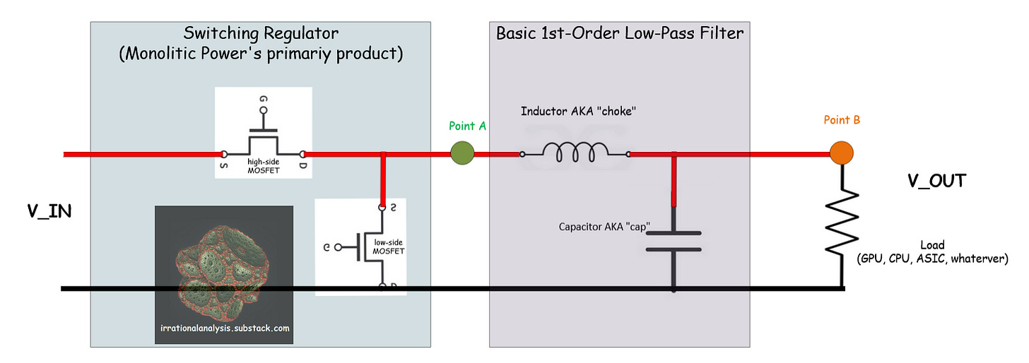
Here is a mediocre diagram I threw together in Visio.

A switching regulator is a device that uses pulse-width modulated signals to step down DC voltage. Oversimplified, it is basically two very beefy transistors that can handle a lot of power.
The output of the switching regulator (Point A) oscillates between the input voltage (V_IN) and ground. Modern switching regulators are highly programmable and have sophisticated current/voltage/temperature monitoring alongside a long list of safety features. This is because the failure mode is fire.
Obviously, shoving brief bursts of 12V into chips designed for ~1.2V is not going to end well. This is where the analog filter comes in.
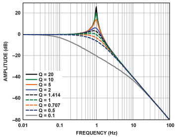
Most VRM designs use a simple 1st-order LC (inductor + capacitor) filter.

The low-pass filter’s job is to smooth out the switching regulator output into something useable for the load chip.
Often, a single switching regulator is not good enough. The output voltage ripple is still too drastic.
This is where multi-phase designs come in.
You take multiple switching regulators, place them in a small time offset from one another, and combine the filtered outputs at the end.
[2] PCB Analysis
Here are some resources:
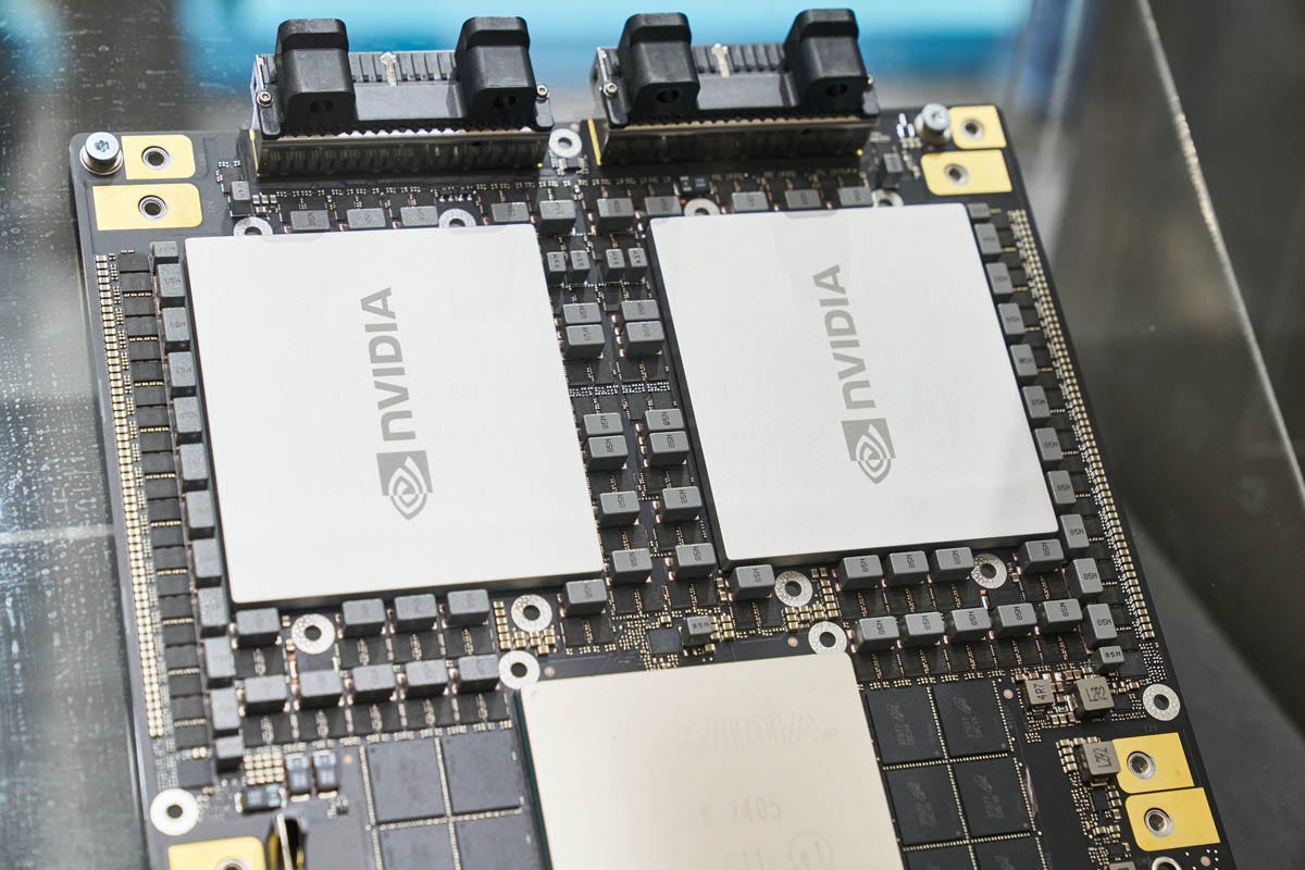
The big rectangles are inductors. Some designs use cylindrical electrolyte capacitors you may be familiar with. Other designs use high-performance (expensive) multi-layer ceramic capacitors, commonly referred to as MLCC.
Here is the fabled GB200 board that buy-side is salivating over.
Let’s zoom in…
You can literally look at the board and spec sheet and reverse-engineer the entire VRM with ease.
High-power chips need a lot of VRM phases to smooth out ripple and deliver the power at reasonable efficiency. There exists a sweet spot.
[3] Walkthrough of Public MPWR 0.00%↑ Datasheet
Let’s look at a Monolithic Power “100 Ampere” 12V to 1.2V DC-DC power stage datasheet.
Notice how there are multiple curves. The switching speed and V_OUT have a meaningful impact on efficiency.
Also notice that the peak efficiency is around 40A load current. Just because the power stage is marketed as “100A” does not mean anyone is actually going to run it at that kind of load.
This is why having multiple phases is so important. Efficiency goes to shit if a power stage is overloaded.
Modern power stages have many safety features. These are important. The failure mode is fire inside your expensive AI accelerator datacenter.
Automatic current and voltage regulation (monitoring and adjusting) is also important. High-performance GPU/ASIC/CPUs have significant transient load responses.
Here are some oscilloscope measurements from the datasheet.
The scope is in AC-coupling mode to highlight the spikes. Voltage spikes are bad. Monolithic Power is showcasing their product with a particular capacitor configuration to advertise that their solution is good.
A block diagram of the power stage shows what kind of input filtering is built in. This helps board designers know how much they need to clean up V_IN (12V in this case). Integrated input filtering is a nice feature that saves precious board real estate.
[4] There is no moat…
In general, there are three major players in high-current DC-DC power stages.
Monolithic Power
Infineon
Renesas
There are other companies that make switching regulators, such as Texas Instruments and Analog Devices. But they don’t make the super high-power stuff.
Earlier this year, I briefly owned MPWR 0.00%↑ shares, before realizing this is a stupid idea and liquidating the position at a 0.5% loss. There is no moat.
It takes roughly three engineers, one month (at most) to design out a power stage vendor in the event of price negotiations failing.
Signal Integrity
Power Integrity
Layout/Designer
Remember that efficiency curve at the very top of the datasheet?
Let’s say Infineon has a similar power stage that hits peak efficiency at 35A instead of the 40A Monolithic Power provides.
I don’t know this. Infineon has most of their datasheets private because they are cowards.
All you need to do is… add more phases and run the inferior power stages at slightly lower load current.
PCBs have what are called “power planes”. A plane of copper that distributes DC voltage. Making the PCB bigger (to fit more phases) is not that difficult.
Not as simple as “haha make power plane bigger”. Parasitics, EM coupling, and loop inductance are all problems that need simulation.
But it takes 3 engineers ~1 month to get all this work done.
The cost of switching regulators is capped. It is very easy to calculate when it makes sense to dump a supplier (Monolithic Power in this case) in favor of inferior products. Designing out is easy. There is no moat.
I find it very funny how many buyside folks bid up MPWR 0.00%↑ only to panic sell the moment supply-chain whispers invalidated their spreadsheets.
Clearly, none of these people had a clue what the hell Monolithic Power does or what they were buying.
Why was MPWR 0.00%↑ stock bid up to a forward P/E higher than NVDA 0.00%↑?


Oversimplifying the process of board design- very challenging to design and test the VRs under all environmental and load conditions. With that said, one of the vendors you mentioned already crossed the moat.
What about the fact that they use their own variant of a BCD (Bipolar-CMOS-DMOS) process at third party fabs that supposedly gives them an advantage over other power/analog semi mfrs using their own older fabs?
Also what explains the 20+% rolling returns for the past 10 years (long before the AI hype)? That could indicate some kind of moat.
Yes it probably got overhyped but It has always had a high PE historically. Interesting fact that it’s the youngest company in SMH. Second youngest is NVDA! Just shows how hard it is to break into the bigger league in semiconductors.
I don’t know a whole lot about analog/power semis, but if this kind of sheep like selling continues, it sure looks tempting…