
Practical Semiconductor Optical Amplifiers (SOA)
Interesting niche.

Irrational Analysis is heavily invested in the semiconductor industry.
Positions will change over time and are regularly updated.
Opinions are authors own and do not represent past, present, and/or future employers.
All content published on this newsletter is based on public information and independent research conducted since 2011.
This newsletter is not financial advice and readers should always do their own research before investing in any security.
Feel free to contact me via email at: irrational_analysis@proton.me
This post is directly inspired by Vikram Sekar’s excellent deep-dive on InP DFB laser physics.

Go sub to him to get the next part of the series as soon as it arrives.
Broadly, I agree with 90% of the content and just have a few moderate differences in opinion.
First I want to re-cap his work before pivoting to semiconductor optical amplifiers (SOA), a LiDAR and long-haul niche device that may have new use-cases in ultra high-power CPO laser market.
And yes, I’m fine.
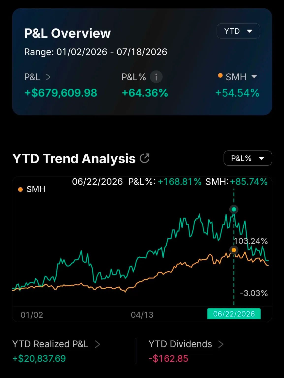


Sometimes I like to zoom out to remind myself I am not completely incompetent.
Contents:
Vik’s Newsletter DFB Recap
“Normal” Optical Amplifiers: EDFA and PDFA
Semiconductor Optical Amplifier (SOA) Basics
Four-Wave Mixing (FWM): Blessing and Curse
SOA for CPO/NPO Market: Featuring Aeva, Active Alignment Hell, and Back-reflection
[1] Vik’s Newsletter DFB Recap
My goal is to describe things from a practical perspective. Physics blah blah blah. Let’s just focus (pun intended) on how thing work and why we would choose to use thing.
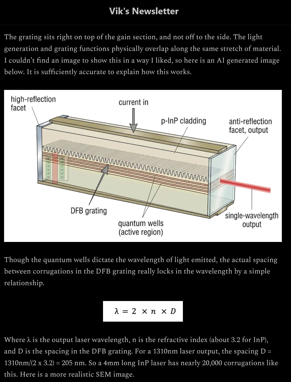
DFB lasers have two parts.
Active region converts electricity to light.
Gratings (tiny mirrors) bounce the light back and forth, recursively amplifying it until the light blasts past the last mirror out of the laser causing it to go pew pew pew.
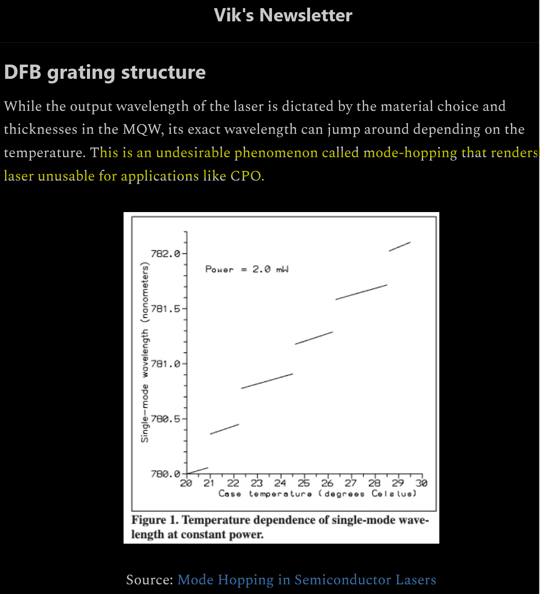
Mode-hopping is not just undesirable. It is death. Most transceiver link flaps are laser mode hops. People go to great lengths to design test lasers and find “mode up free” regions in the LIV curve.
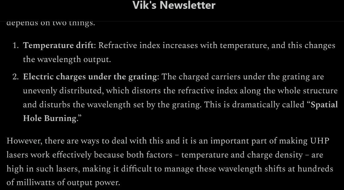
Temperature drift effects wavelength much more strongly than drive current. As a rule of thumb, 0.1 nm/kelvin drift is common. As Vikram mentioned before, the grating design/spacing determines the laser wavelength, but there is manufacturing variation Thus in a real system, heavy temperature tuning is necessary. Imagine a ELSFP module with 8 wavelengths. Each DFB is designed to operate at 40C but may be operating at any temperature within +/- 10C at up to two decimal point accuracy. 39.85, 45.11, blah blah blah.
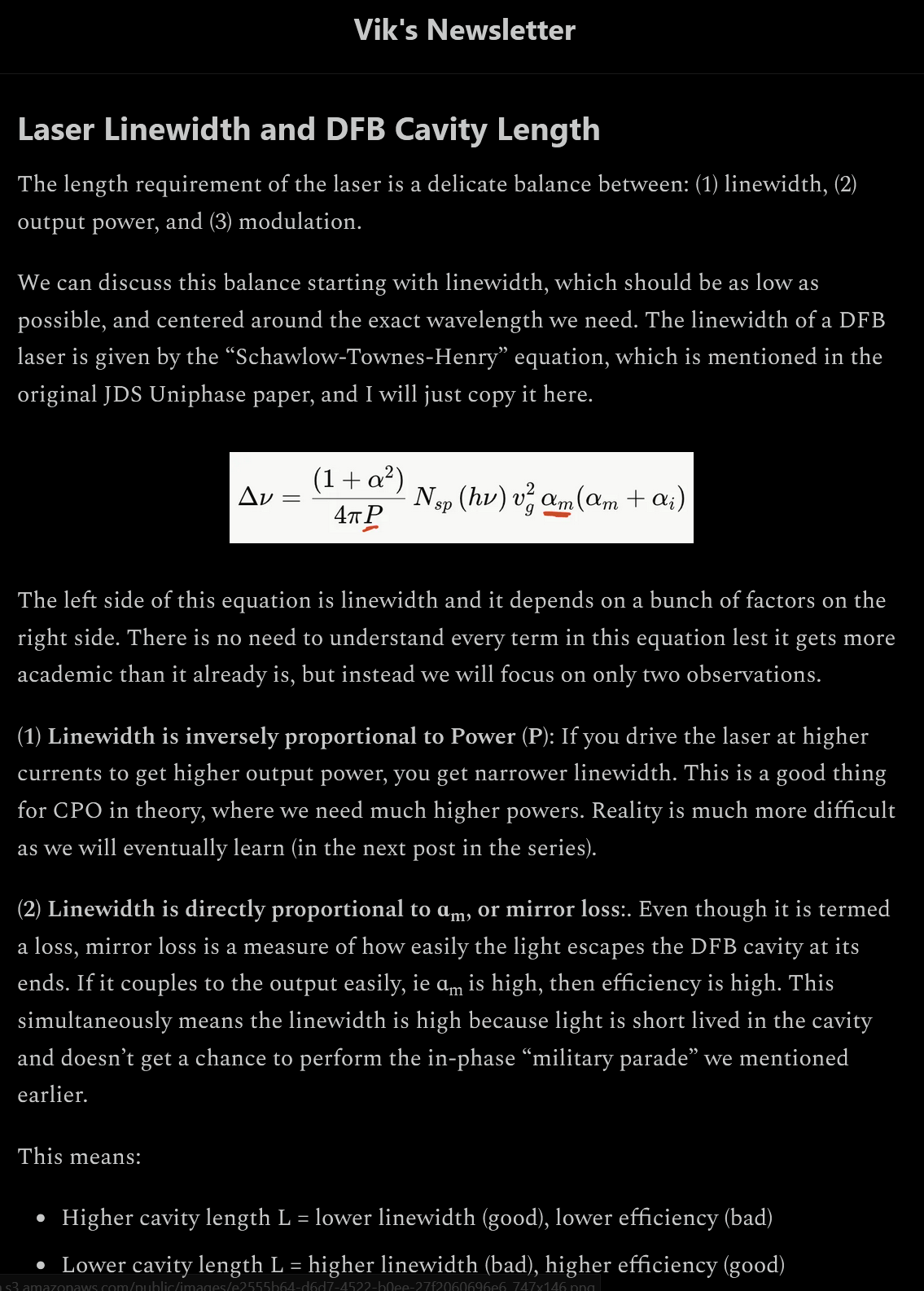
Everything Vikram wrote is correct but he is missing two critical topics.
Laser reliability (does thing burn itself out after running 6 months) depends on charge density within the cavity. A shorter cavity at the same output power means higher charge density and serious reliability concerns.
Mode-hop risk (how likely the laser is to flicker) scales with cavity length.
This is absolutely critical to understand. Lumentum and Broadcom can achieve acceptable linewidth for CPO/NPO applications at around the same cavity length. Not only does this save them money (more chips per InP wafer), it also drastically reduces mode-hop risk. All competitors need around 60% longer cavity length which makes the lasers at far higher risk of mode-hop/instability.
[2] “Normal” Optical Amplifiers: EDFA and PDFA
Suppose you have an optical signal and need amplification. What is the default solution?
If you are in C-band, this is called EDFA.
If in O-band, this is called PDFA.
They are usually depicted as a spool in block diagrams.
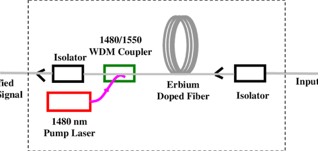
This is because EDFA/PDFA are indeed long-fibers that have been doped with fancy materials.
Broadly, the performance of these amplifiers is excellent. Lots of gain and very low noise figure.
The problem is cost and physical footprint.
[3] Semiconductor Optical Amplifier (SOA) Basics
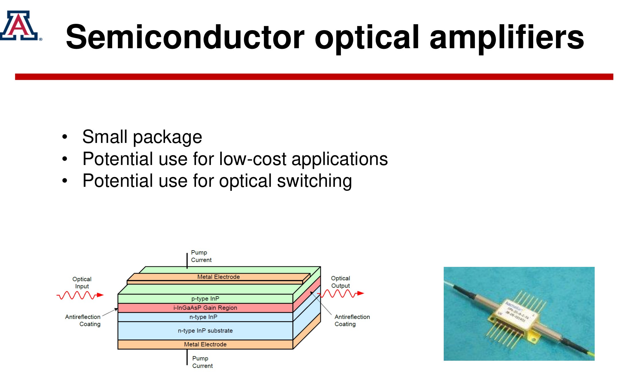
SOA is basically a DFB laser without any gratings.
This type of amplifier is more noisy than a PDFA/EDFA but is tiny and dirt cheap (relatively). It also has some properties that are either a blessing or a curse depending on what you are trying to accomplish. More on that later.
First let’s go over the basics on how these SOA things work and behave.
ASE = amplified spontaneous emission = crap SOA outputs if you turn it on but dont have any input optical power.
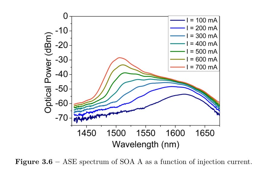
ASE goes down if you seed with something at the input.
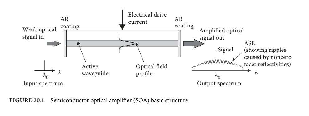
Traditional applications of SOA (long-haul comms, LiDAR) involved seeding a very weak signal (say -25 dBm to -5 dBm) such that the small signal gain of 20-30 dB boosts the output to around 13 dBm at most, typically lower.
Think using a demux in a long-haul DWDM system to pick out one wavelength and amplify it.

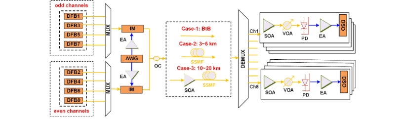
Note that only one wavelength of light enters the SOA in the vast majority of traditional applications. This is important.
[4] Four-Wave Mixing (FWM): Blessing and Curse
All amplifiers have intrinsic (common sense) impairments.
Amplify input noise.
Add additional noise. (typically from driver)
Add non-linearity.
Optics is different because fuck you. There are these “non-linear” impairments. I have no idea what non-linear means but let’s roll with it.
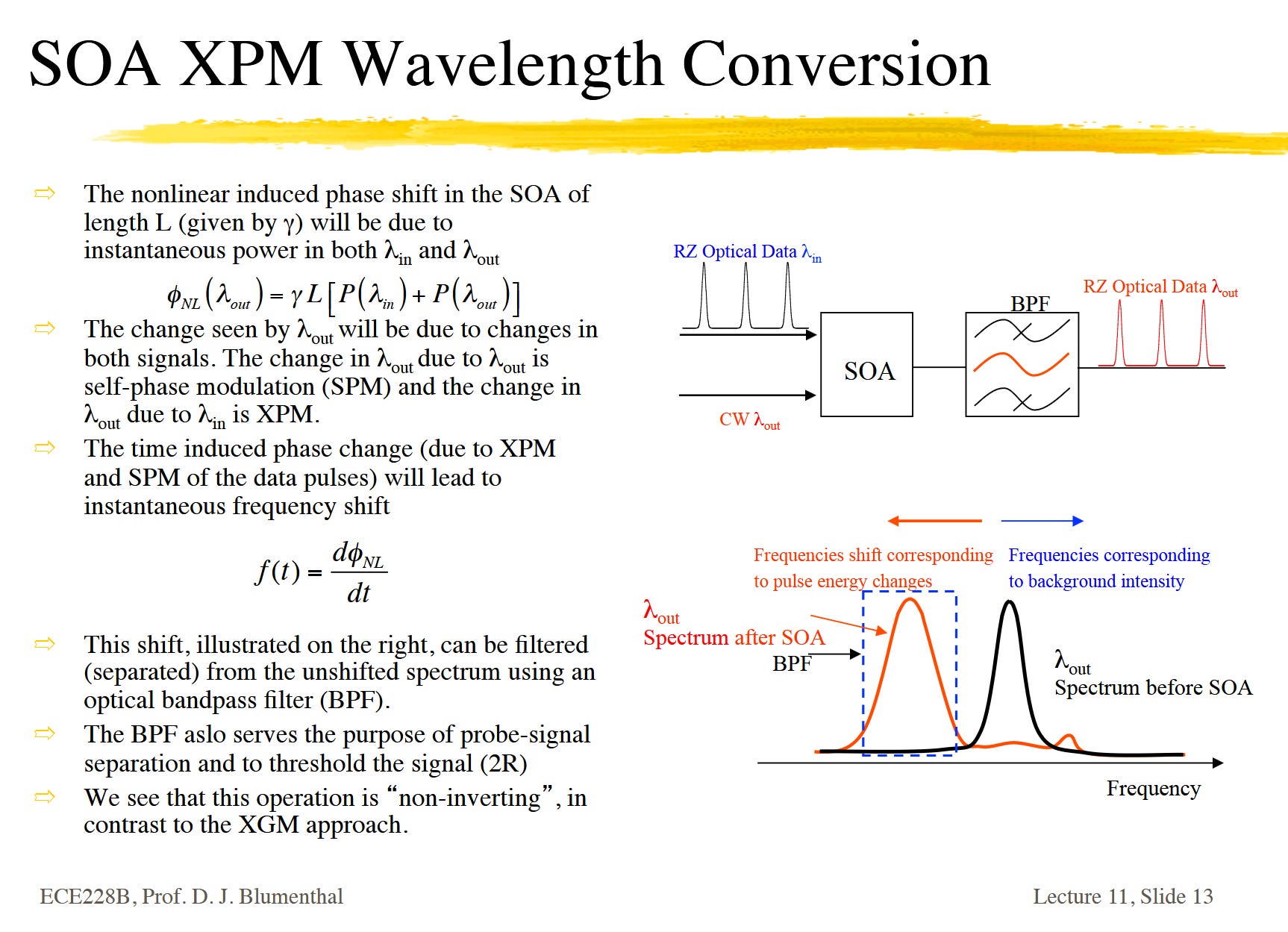
One of the more notorious non-linear impairments is four-wave mixing (FWM). This process happens in basically every medium (glass fiber, SiPho PIC, SOA, EDFA, whatever) but is much stronger in certain situations.
FWM shows un in optical fiber…. after a few kilometers.
FWM happens in SOAs in a meaningful severity very quickly.
FWM scales quadratically/cubicle with input optical power and cavity length. It also scales based on how close your wavele3ngths are together. Tighter spacing is exponentially higher FWM efficiency.
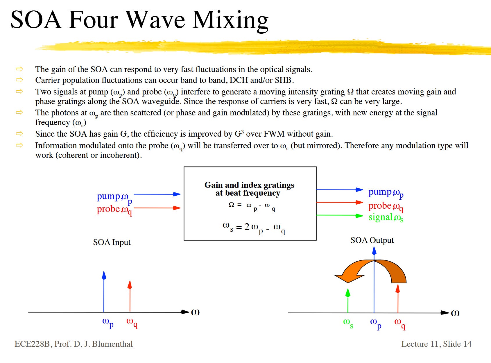
So what am I talking about? Let’s look at an example where two wavelengths enter and SOA.
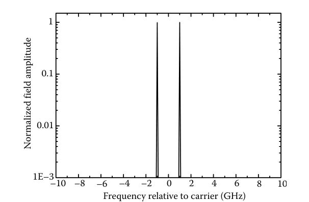
Intuitively, you would think the output of the SOA would be those two wavelengths amplified with some broadband noise assed.
WRONG.
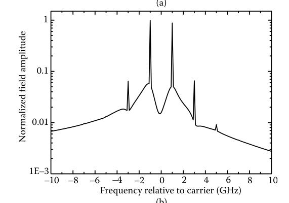
Because of physics reasons, some of the photonics teleport to create two extra junk spikes on the sides. The spacing of these junk spikes depends on the spacing of the input signals. Also, these spikes have conjugate phase, which means the frequency domain spectra is flipped. Unless you are intentionally trying to use this information to back out chromatic dispersion, this is bad. Conjugate phase noise spikes is not helping the situation.
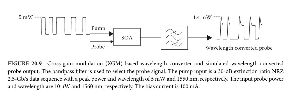
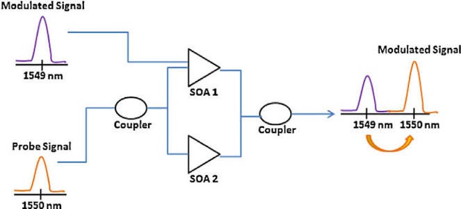
FWM is either a blessing or a curse. You either want this to happen in order to accomplish useful tasks such as wavelength conversion.
Or you want to avoid this shit like the plague.
CW laser amplitude noise (RIN) is defined as an integration from 10 MHz to Nyquist frequency. The lower 10 MHz cutoff is due to photodiode and TIA responsivity. Any noise that slow in theory does not matter.
[5] SOA for CPO/NPO Market: Featuring Aeva, Active Alignment Hell, and Back-reflection
So far 5 investors have pinged me about AEVA 0.00%↑, a LiDAR shitco, because sell-side picked up on this SOA thing. Let’s back up a bit.
Traditional long-haul datacom systems only need 20 to maybe 100 mW output power.
LiDAR needs much more power so all the high-power (400 mW and above) SOAs on the market are from degen shitcos desperately trying to pivot. Aeva is one such pile of flaming dogshit.
The Aeva SOA is quite good. Rated to about 650 mW output power with excellent properties (WPE, low ASE).
In theory… someone could take weak 20-100 mW discrete DFB lasers and just put an Aeva SOA (or similar) behind it to amplify up to 400 mW. Boom, CPO/NPO viable laser using crap low-power lasers.
There is nuance. Calm down finance friends. It’s really funny how excited finance people get over detritus that has a chance to re-rate from a total business pivot.

There already is a strategy called MOPA (main oscillator, power amplifier). Take one monolithic InP chip. Print a low-power (100 mW) DFB then add a short waveguide then add a SOA.
Furukawa has a MOPA targeted for CPO/NPO. Coherent is pivoting to MOPA after botching their UHP DFB.
So why is this MOPA thing not super common? Why are the two dominant UHP laser players (Broadcom, Lumentum) not using this strategy?
First, it costs more. A lot more InP area.
But the real reason is HORRIFIC MODE HOPING DUE TO THE CAVITY BETWEEN THE DFB AND THE SOA.
DFB lasers are very very fucking sensitive to optical back-reflection.
Any light that gets reflected backward goes into the gratings and destabilizes the shit out of the laser.
This is why there is always a isolator between the DFB and whatever it is shining light into.
Optical isolators are (well try to be) one-way gates that let light go forward but not backwards. You can’t have an isolator on a monolithic InP MOPA chip because of manufacturing limitations. The isolators are made of materials not InP. Terbium whatever.
https://www.coherent.com/news/glossary/faraday-rotators-and-isolators
Fun fact, COHR 0.00%↑ makes around 60% of the worlds isolators I think.
Anyway. MOPA bad because mode hop issues that are kinda unfixable. All you can do is mitigate and pray this shit passes reliability testing.
Using a discrete SOA in conjunction with a DFB solves this issue. So why has no one done this? The answer is simple. Cost.
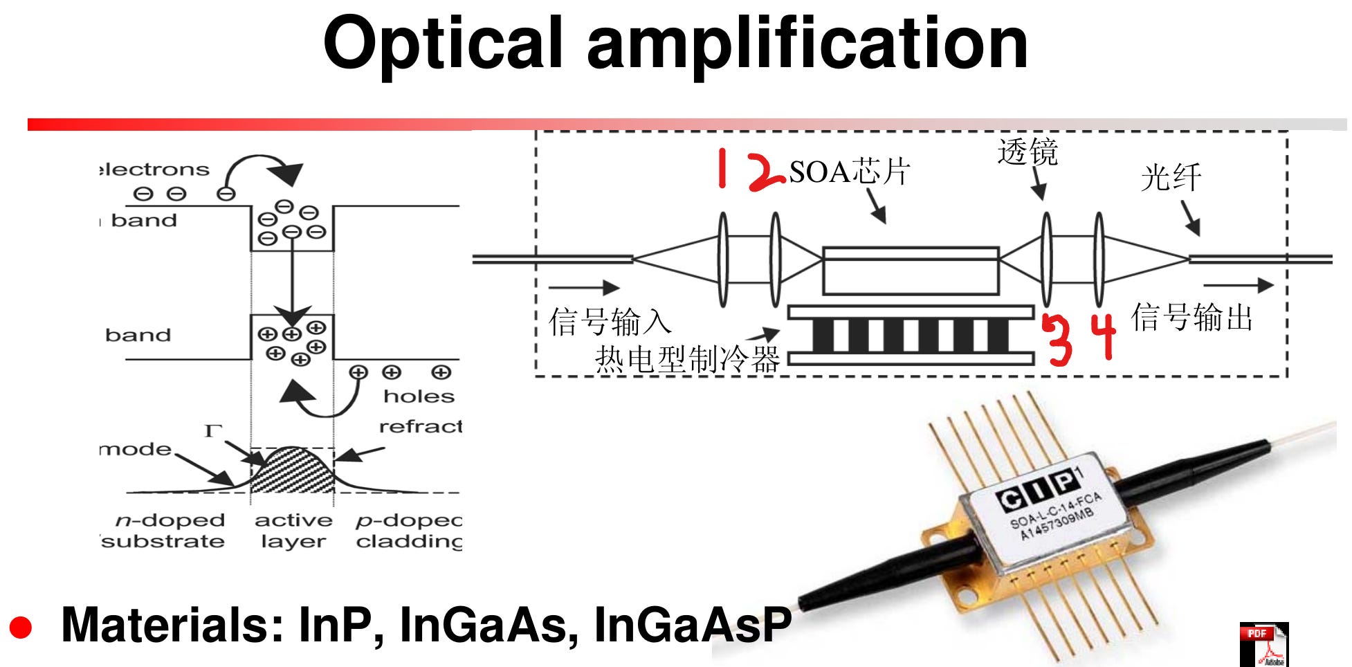
You see that? Four lenses. The isolators are missing from the above diagram too. An isolator between the DFB and SOA input is a must. Isolator on the output you can skip in theory but it’s tricky.
Each element in an optical path (DFB, lenses, isolator, SOA, fiber, PIC, whatever) generally requires active alignment, an expensive process that requires specialized equipment (FiconTec or custom) to align with low single-digit micron accuracy and less than 2 degrees angle accuracy.
This shit is expensive and it gets out of control real quick. Just with some napkin math, a 8-wavelength ELFSP module using shitty lasers and Aeva (or equivalent LiDAR shitco SOA) requires…
8x 20-100 mW DFB
8x 400-650 mW class SOA
32-40 lenses
8-16 isolators
56+ active alignments

On the surface, this seems completely retarded. But… the CPO/NPO market is so starved that any functional supply will sell. If we call Broadcom and Lumentum module-level (ELSFP) gross margins at 50-65%, I can see a half-dead LiDAR shitco partnering with TFC or Fabrinet to sell the same thing with worse power efficiency at 5-20% gross margin.
If anyone knows which InP fab (please let it not be CPFC) Aeva uses or their SOA cavity length, please let me know. It is trivial to model COGS and yield of this stuff.
Essentially, AI demand is so high that there is now demand for new tranches of worse products because we can’t increase the supply of good products in time. Same thing is happening with power turbines, with lots of lower-efficiency gensets hitting the market because there are buyers. I assume these stocks are getting gang banged by hedgies just to play the volatility rather than express any fundamental view of how long worse products will be valuable. If they really believed these will be big companies in 10 years, why is Nvidia’s P/E not at like 100?
I’ll be honest, even most of the terminology goes way over my head.
What are the key takeaways for our stocks and portfolios?