
OFC 2026 Irrational Recap
Glorious conference.

Irrational Analysis is heavily invested in the semiconductor industry.
Positions will change over time and are regularly updated.
Opinions are authors own and do not represent past, present, and/or future employers.
All content published on this newsletter is based on public information and independent research conducted since 2011.
This newsletter is not financial advice and readers should always do their own research before investing in any security.
Feel free to contact me via email at: irrational_analysis@proton.me
So much amazing stuff. Honestly barely covering half of what I want to cover.
I realize the audience here is rather varied. There are engineers and students who care about technical stuff. Then a wide variety of sophisticated investors. Then the retail and pod-monkey idiots who want to ape into shit.
Hopefully the material is organized such that every group gets something useful out of this.
MESSA SO EXCITED!
LETS GO!
Contents:
Key Useful/Investable Topics (randomized order)
VCSEL CPO: Cope and Nuance
Semtech CTLE (Mediatek TPU Probably Doomed)
Lumentum To The Moon
Huber Schuner OCS
Nvidia Super Overkill Transceiver
Broadcom/Meta CPO Reliability Update
I DESPISE MICRO-LED IN ALL FORMS
Optics Reach and Credo Dilemma
Marvell Seems Panicked: Anti-DSP Jihad Response?
Tower vs GloFo Sipho: NOT EVEN CLOSE
Apology to Zephyr on Furukawa Laser
AAOI Booth
400G EML vs SiPho
Impressive Ciena Presentation
Incredible Santec Tunable Laser
Arista Super LPO (XPO)
Cool Shit
Public Markets: Re[tail]-Tard and Pod Monkey Summary
Trading Account 3/27/2026 Snapshot
[1] Key Useful/Investable Topics (randomized order)
There is no meaning behind the ordering. I made this up stream of consciousness and was too lazy to re-order.
Skip to whatever you find interesting. Read it all. IDK.
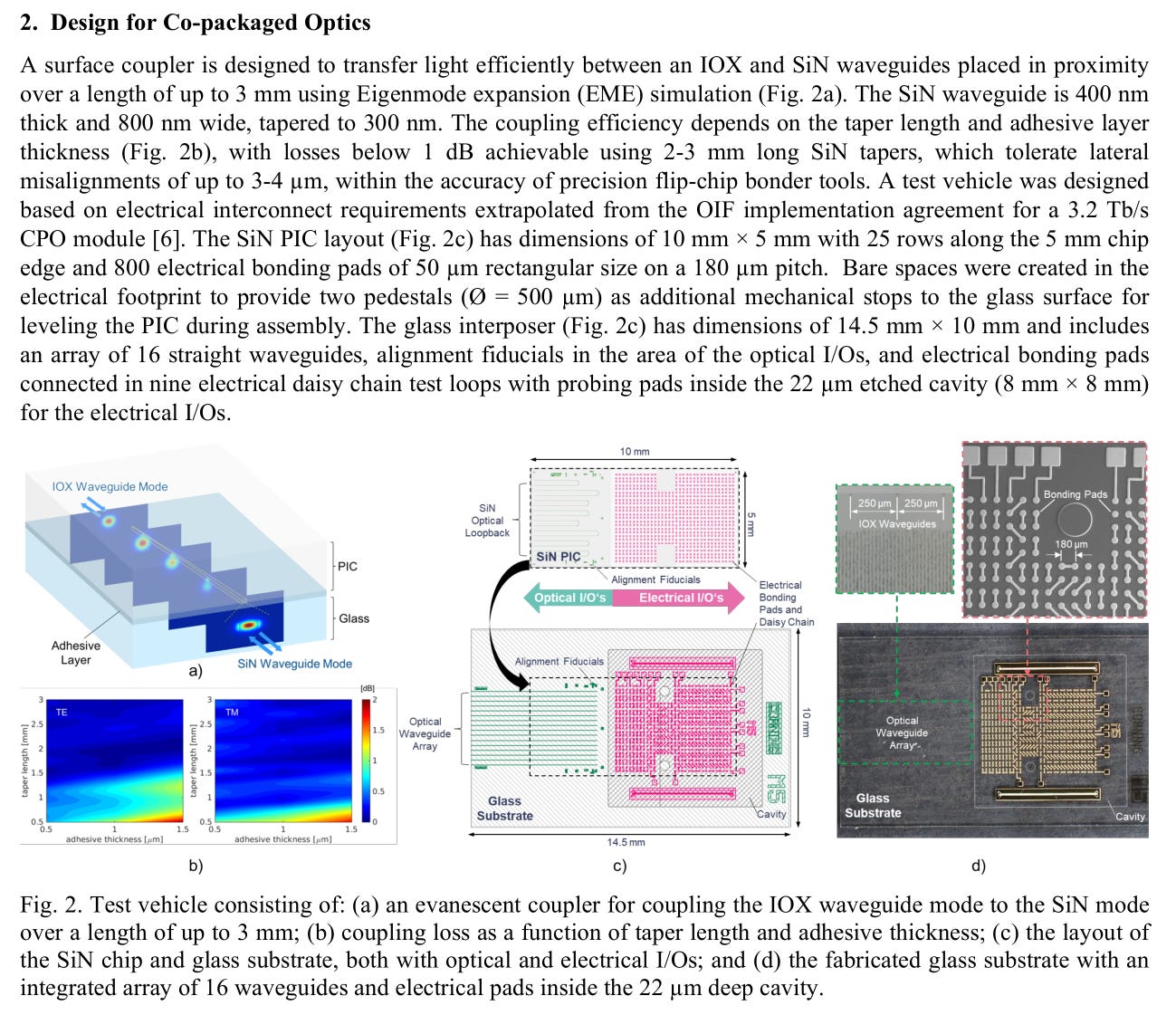
[1.a] VCSEL CPO: Cope and Nuance
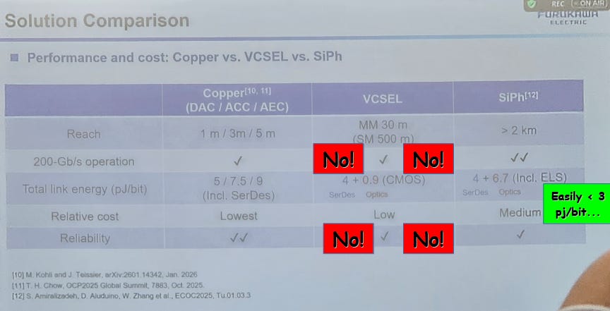
I don’t like VCSEL CPO/NPO, but willing to admit it could be viable if done right. The details matter.
In a way, only one attribute matters, data rate of the VCSELs.
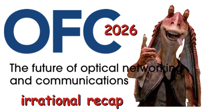
VCSEL cannot go above 112G per lane. There are major reliability issues.
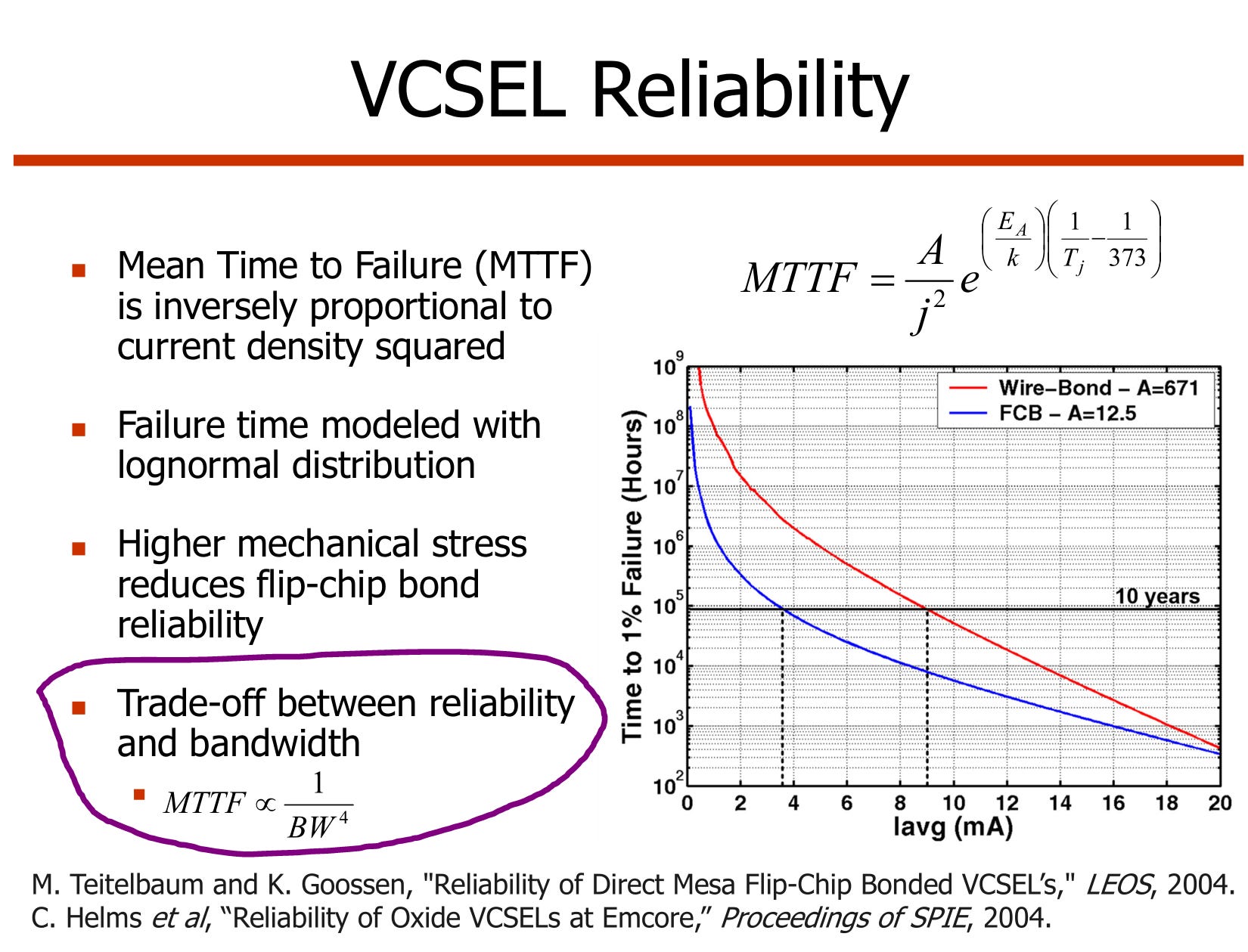
While there were several presentations on 200G/lane VCSEL (can it perform, bandwidth limits), NOBODY address reliability concerns. I find it amusing people give shade to sipho-based CPO reliability but ignore the massive problems 200G VCSELs face.
You can see Coherent presenter have a brief moment of self-awareness before reverting to the (wrong) stance that 200G VCSEL can work.
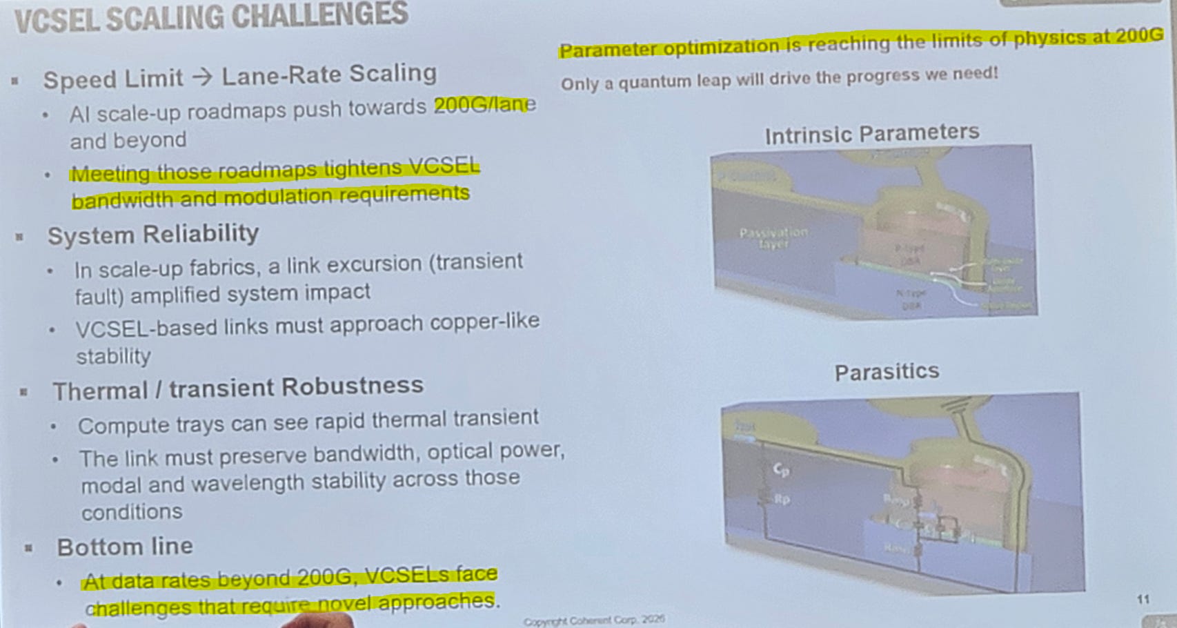
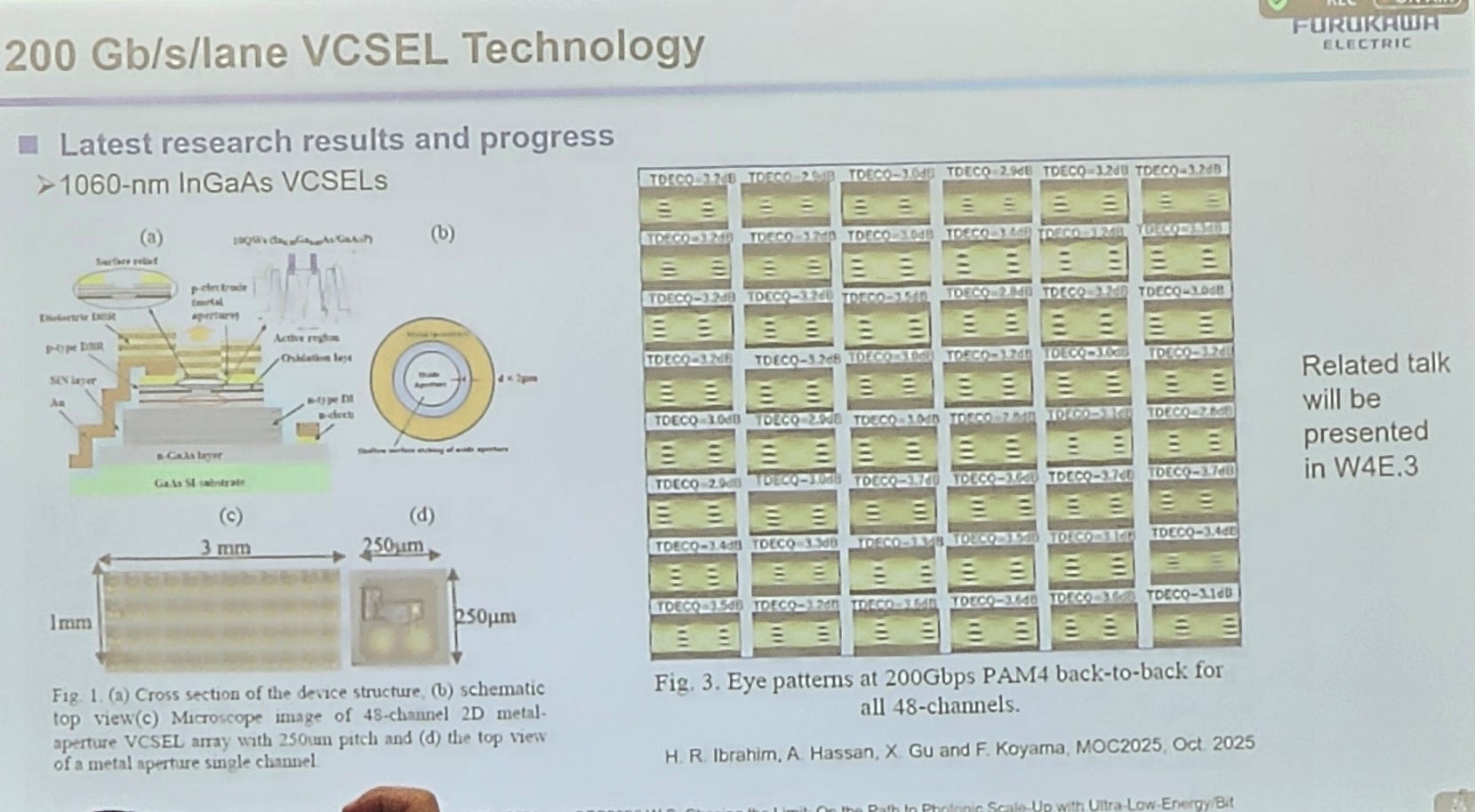
Next, we have Furukawa.
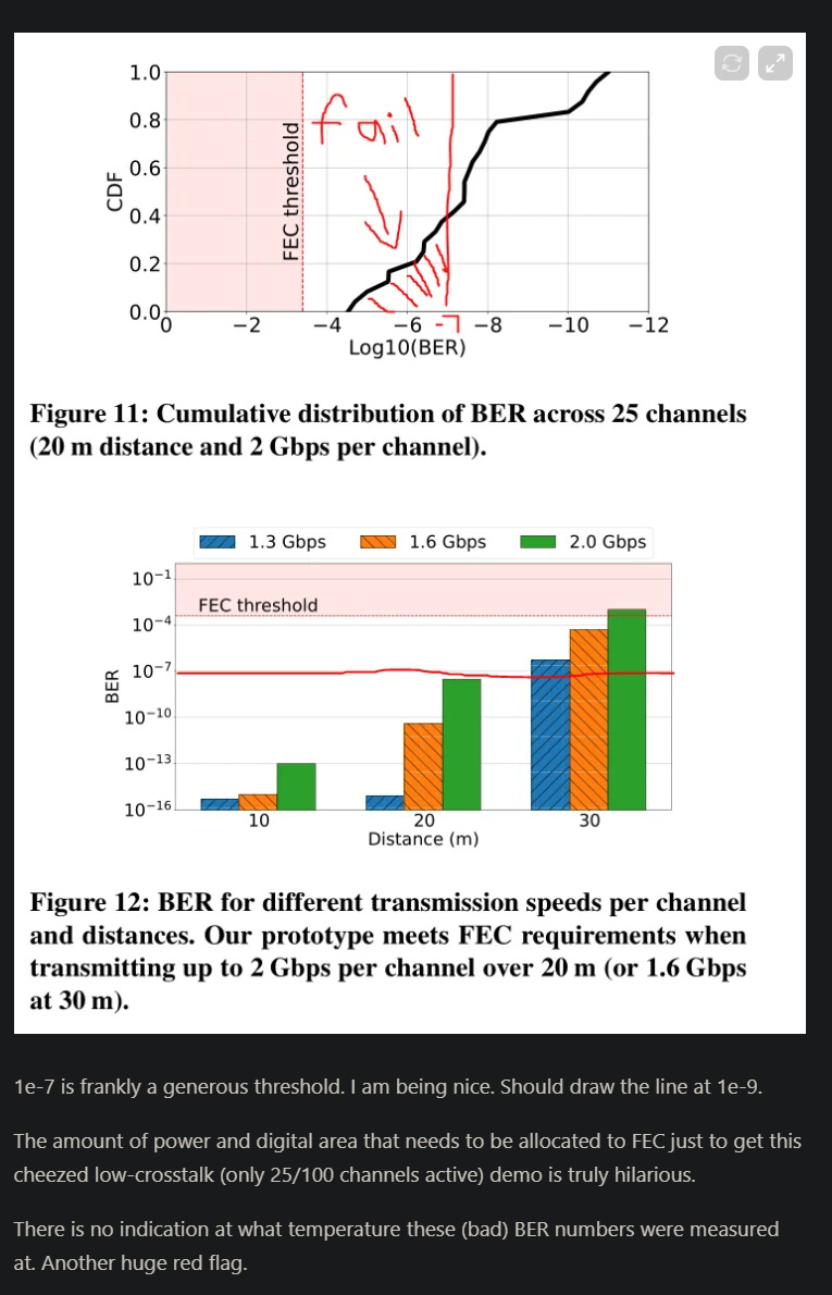
Thats an… ok eye you have there. Show me what it looks like with all lanes active, dumping crosstalk/noise into each other.

ENCHANCE
A TDECQ at 3 dB or higher is an outright failure. Real commercial products have TDECQ of ~1.7 dB or lower in datacom, 2.5 dB or lower in telco/longhaul.
So Furukawa is displaying a 41/48 = 85% failure rate lol.
Credit to them for actually showing this data.
ENCHANCE MOAR
Here is a random eye I picked.
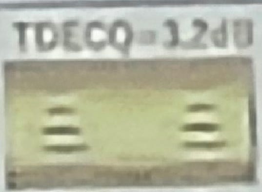
It’s quite bad. This is what the eye of a SerDes that has suffered catastrophic ESD damage (fried transistors) looks like. Terrible RLM. To my eye (pun intended) seems to be < 0.75 RLM.
Now that we have established 200G VCSEL is a bad idea, let’s focus on how “slow” the VCSELs should go.
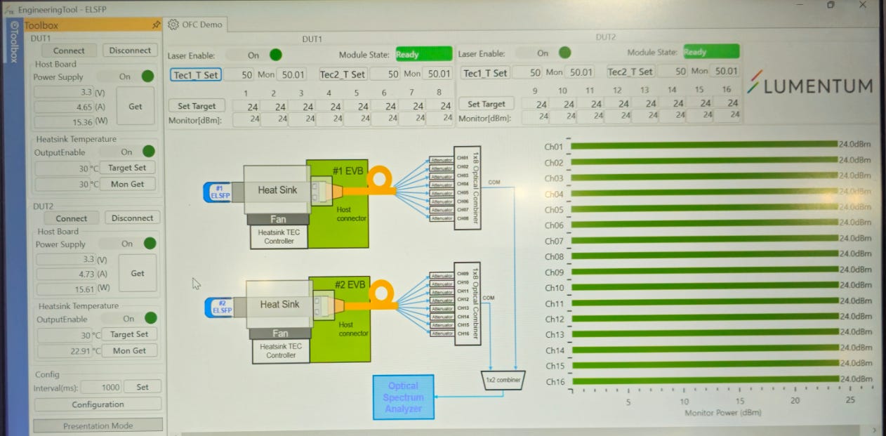
Here is Lumentum’s 32G NRZ per lane demo.
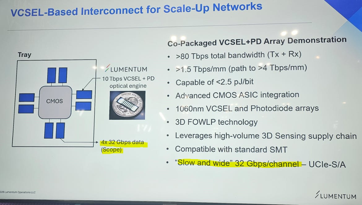
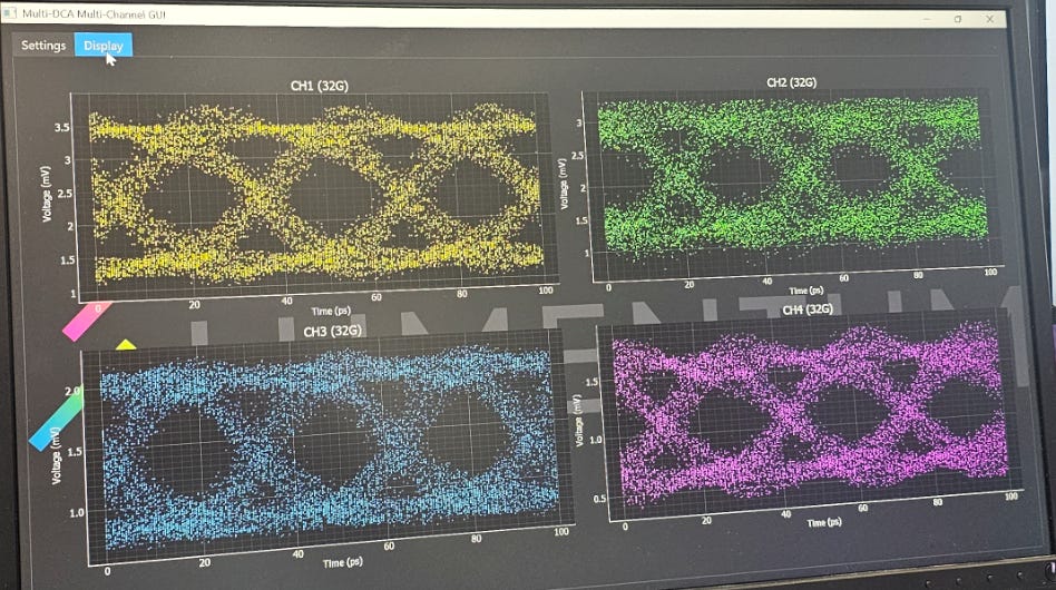
These results are frankly mediocre. Only four channels are active and channels 1+4 are aggressively over-peaked.
Because the rate per lane is so slow, they were forced to have very high density and thus the system is much more susceptible to electrical crosstalk.
Coherent also had a VCSEL NPO/CPO demo but theirs ran at 100G per lane.
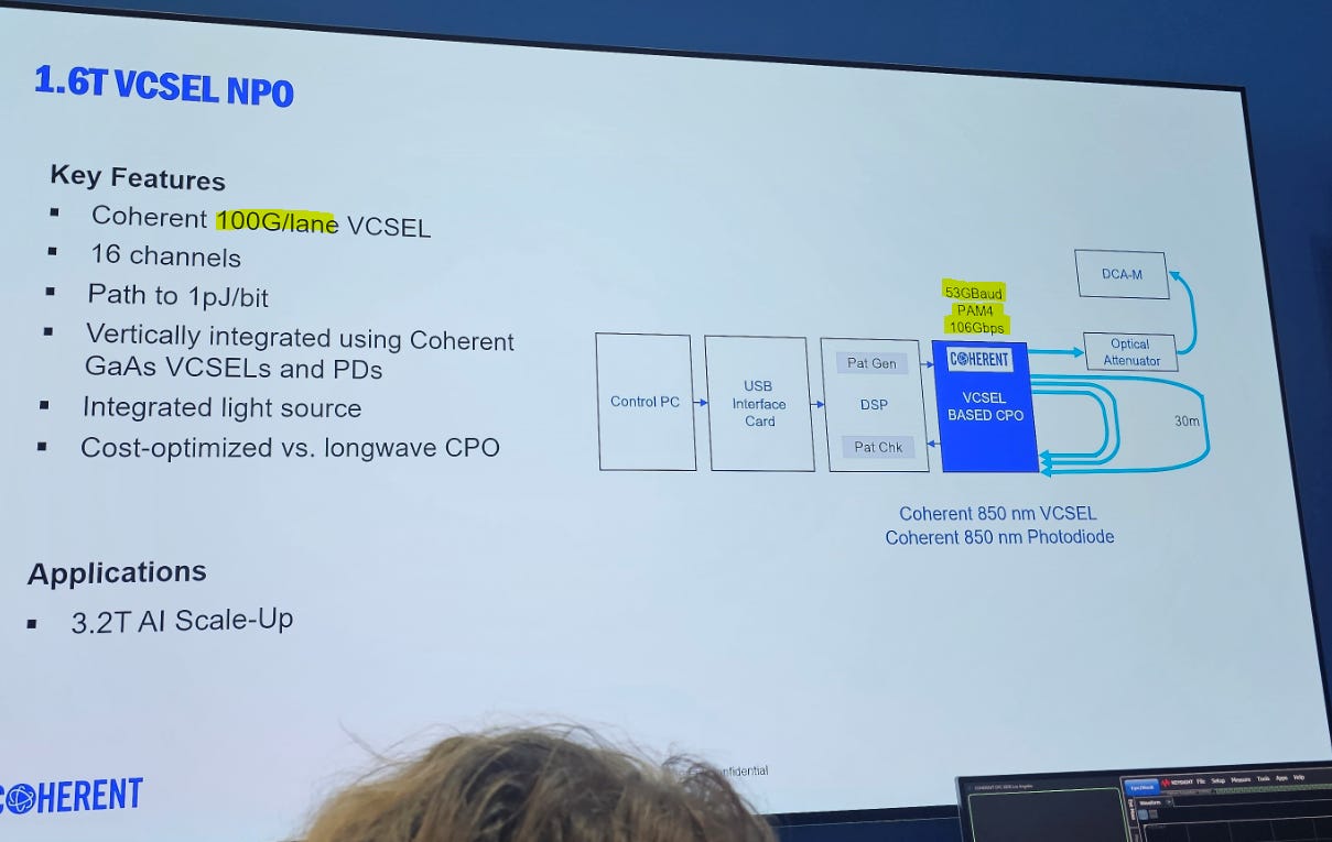
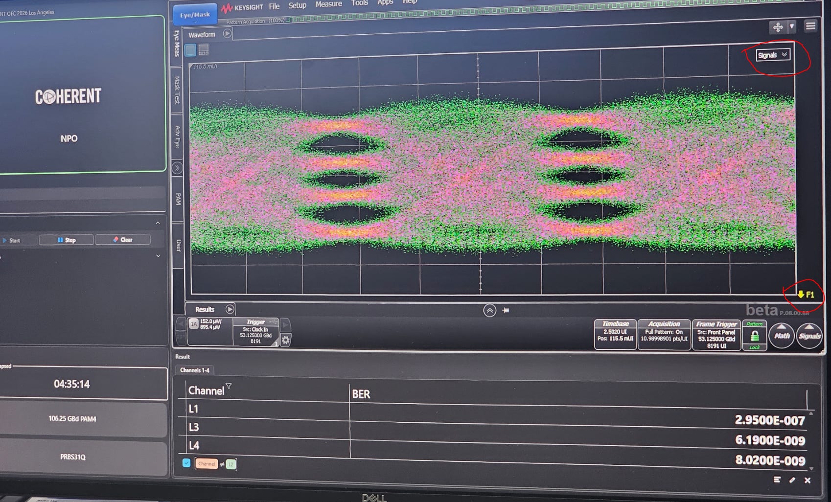
I am annoyed they are hiding the math function(s). Would have been nice to see the TDECQ instead of BER.
But overall, this approach is better than Lumentum’s 32G/lane VCSEL NPO/CPO.
In my opinion, the “correct/optimal” rate for VCSEL NPO/CPO is either 64G NRZ or 112G PAM4.
Still don’t like this category of solution but willing to tolerate it’s existence. Engineering is about choosing the right tradeoffs and problems to tackle. SiPho better but wish VCSEL friends luck. You guys gona need it.
[1.b] Semtech CTLE (Mediatek TPU Probably Doomed)
Previously, I had a tinfoil hat theory that Mediatek TPU could only work if they used a huge amount of Semtech CTLE (linear equalizer // “the ACC chip”) across both cables and PCBs.
For months I have been trying to get the damn datasheet for this part. Legit impossible.
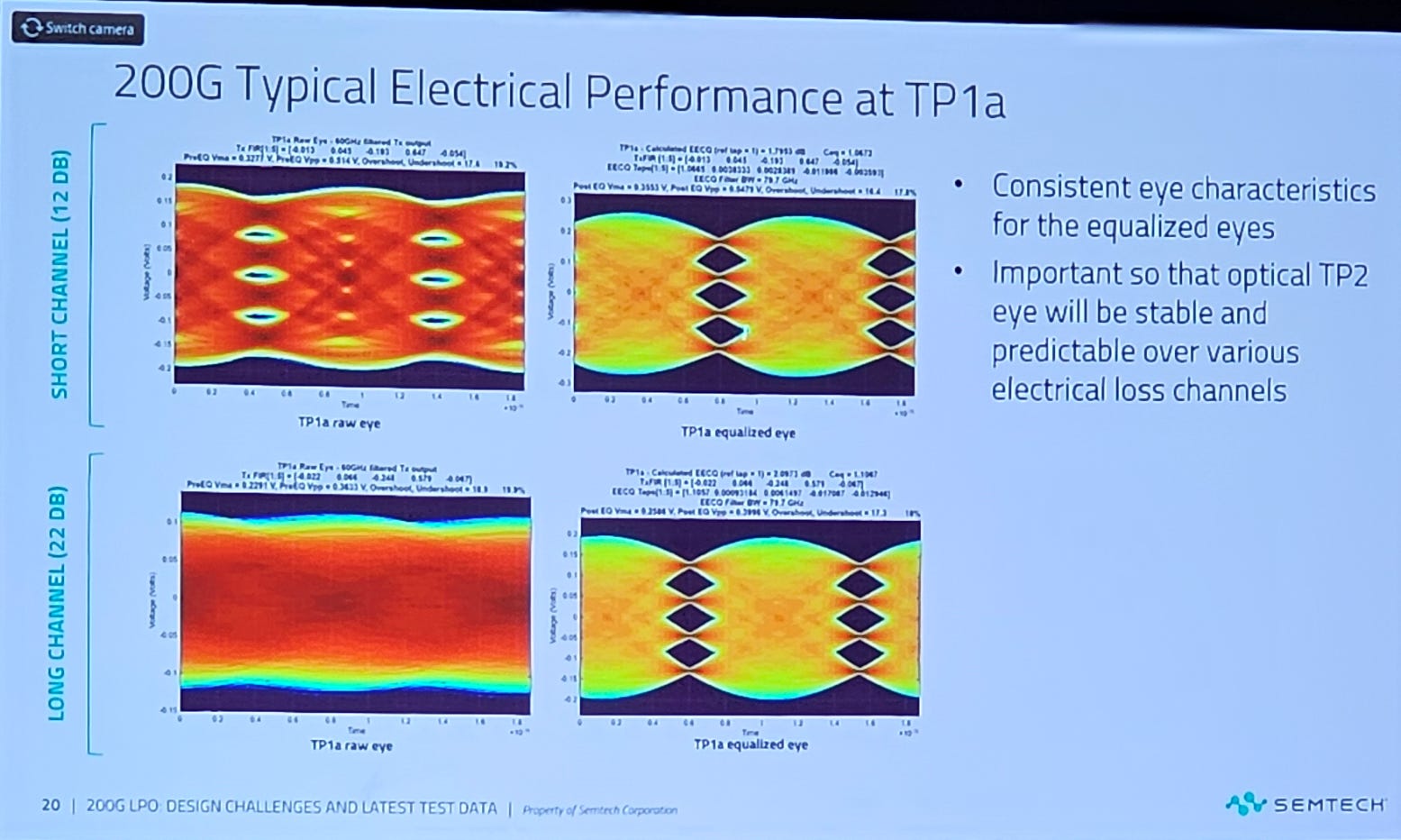
But… finally got the curves I was looking for at the Semtech LPO presentation.
For context, basically the same Semtech chip goes into LPO, ACC, and potentially on-board. It’s just an analog amplifier. A damn good one.
These analog amplifiers (CTLE) are very sensitive to input power.
Too little input power and they just add noise.
Too much input power and they get saturated and kill linearity.
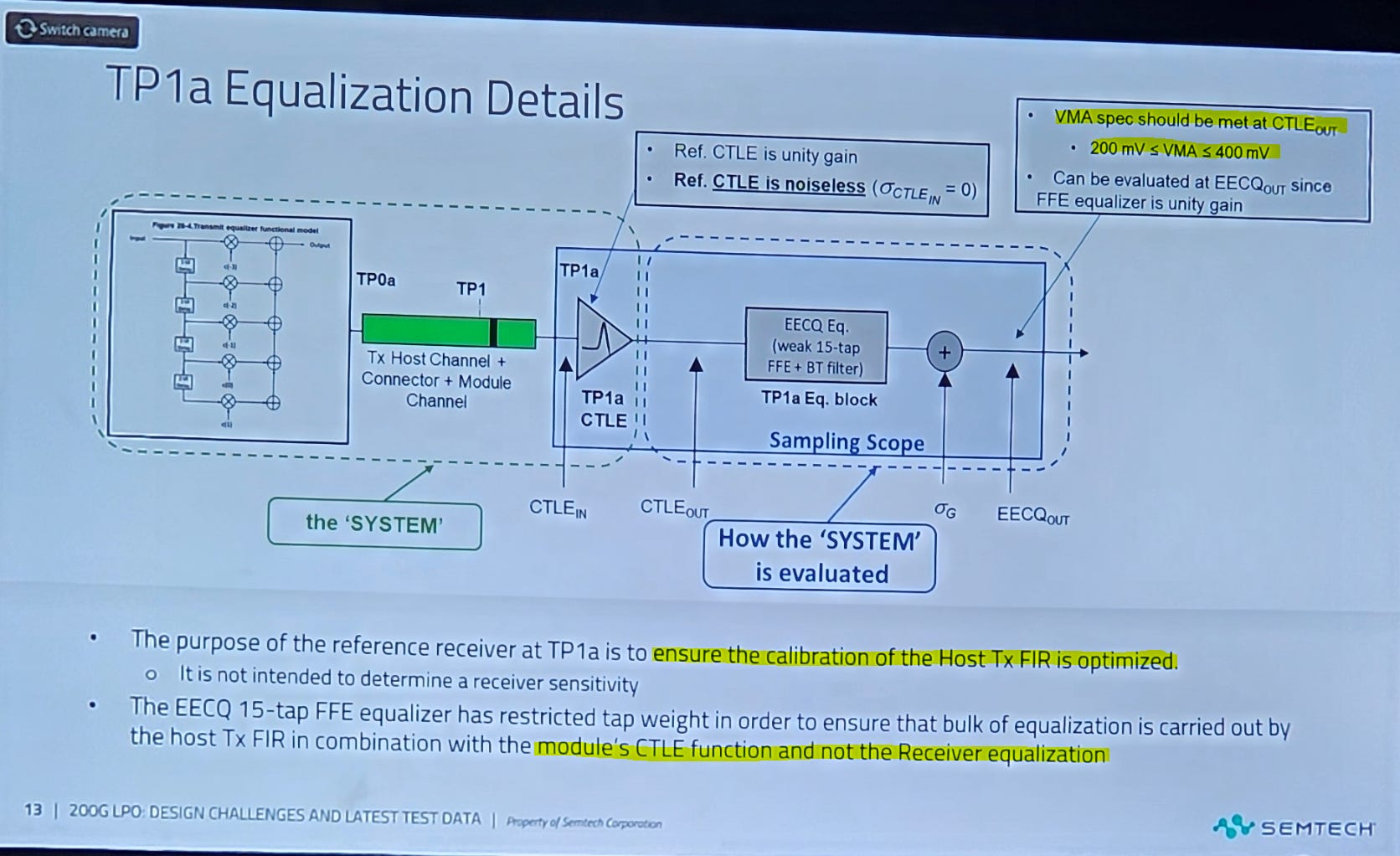
It is absolutely critical that the link-training algorithm adjusts the Tx FFE to optimize the Semtech CTLE independently of the receiver EQ (CTLE + FFE + DFE).
In other words, this shit is difficult. Painful.
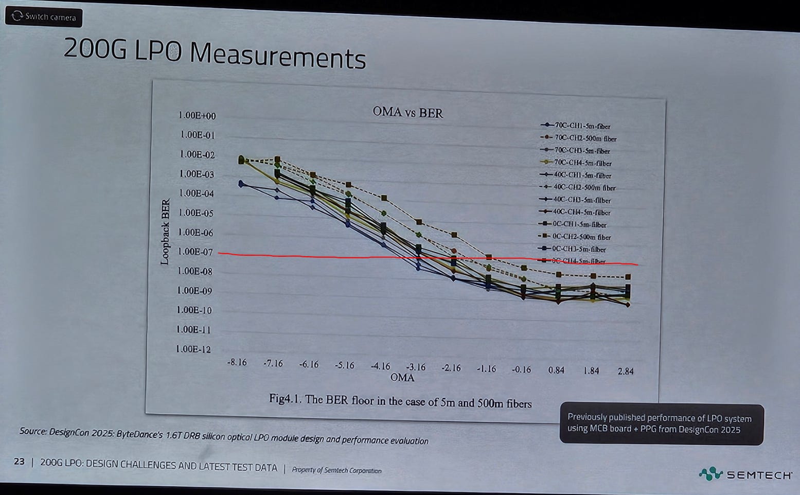
But.. the results are incredible.
Now here is where the complexity comes in. Look at this example.
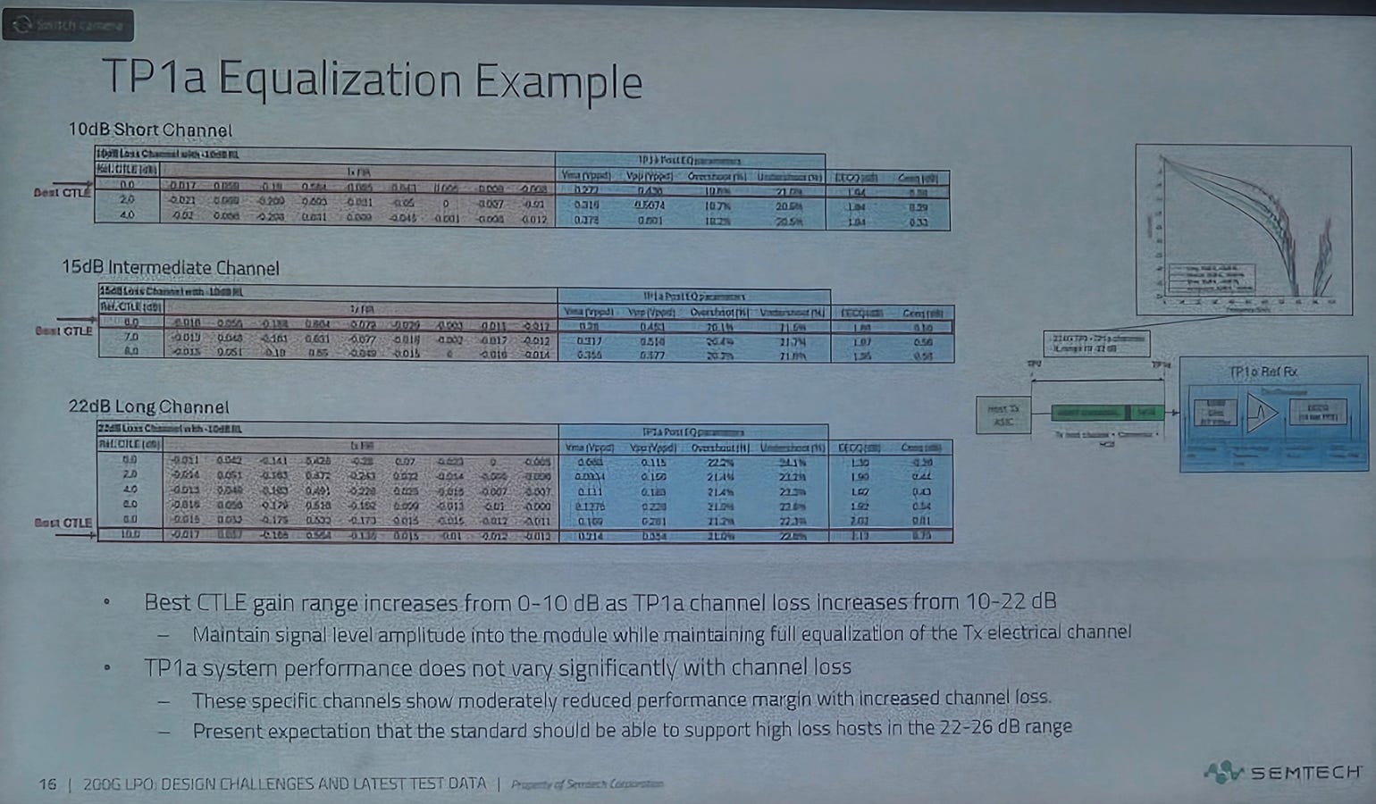
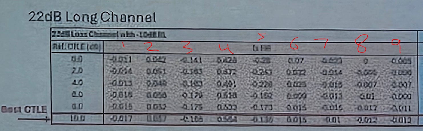
In this example, the Tx FFE is 9-taps which is frankly unrealistic. Real modern systems have 5 taps.
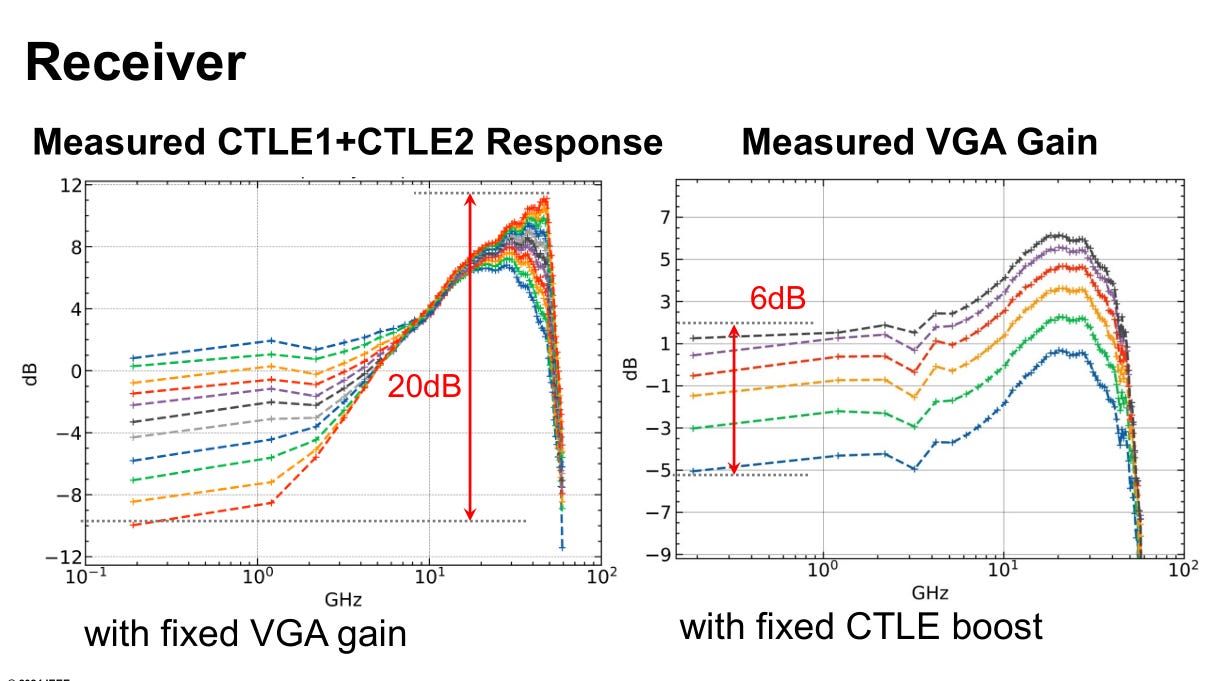
As you can see, there is only one programmable parameter for the CTLE.
Every modern SerDes also has a CTLE. Often multiple stages of CTLE. The reason is that tuning the shape of this response is critical to optimizing performance, especially across a wide variety of channels.
Here is what the Synopsys CTLE(s) look like.
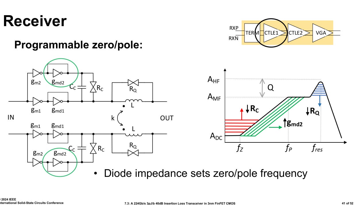
Semtech’s chip does not have these fancy adjustment knobs. Only peaking/gain. This is fine for their target market and honestly somewhat expected. The reason I have been trying to get the datasheet is to confirm my suspicion.
In light of this new information, I am convinced Mediatek TPU is absolutely cooked. There is no way this Semtech chip can save them. Not enough tuning options, particularly at low frequency. That is the real killer and what I was looking for.
To be clear, this is not bad for Semtech stock. It went from a possible ~5X to “only at 2-3x. I own a shit ton of Semtech stock and have high conviction. The nice thing is these chips are useful in copper (ACC), LPO/XPO, NPO, and traditional re-timed transceivers!
All of you debating copper vs optics… there is a name that wins in everything lol.
Also the Semtech chip is way better than equivalent Macom part. If I hear one more finance person tell me people are multi-sourcing Semtech/Macom analog amps and they similar performance I shall scream.
[1.c] Lumentum To The Moon
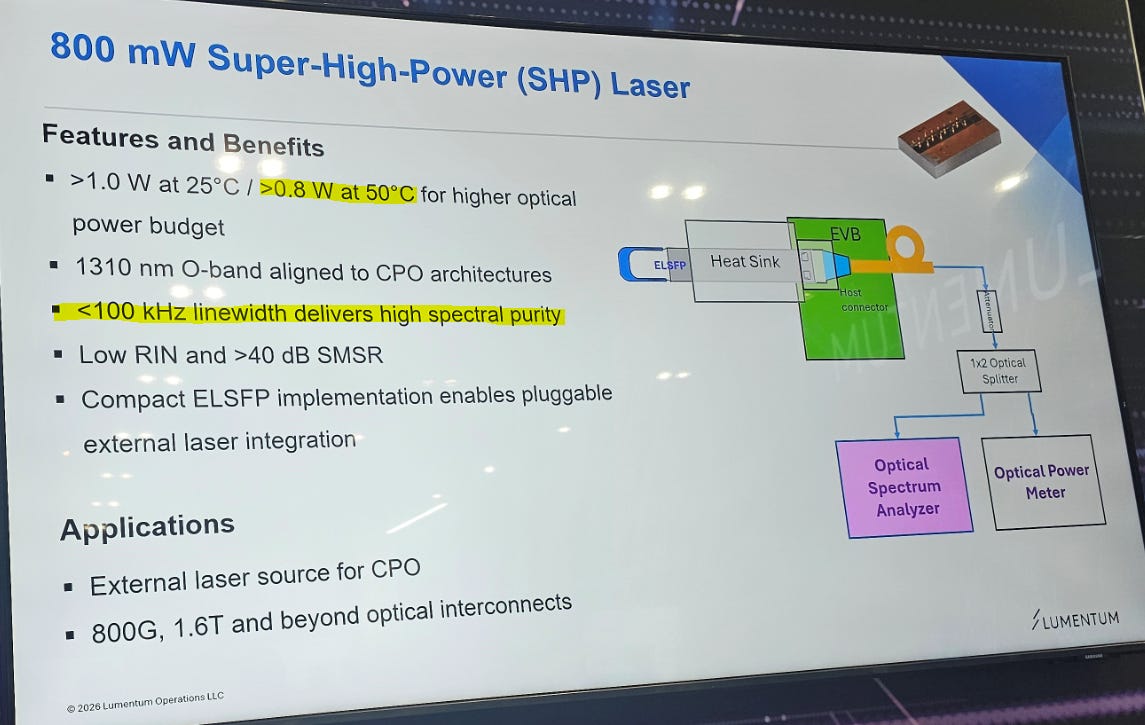
Lumentum is the only high-power (350+ mW class) laser vendor who publicly declares their linewidth spec.
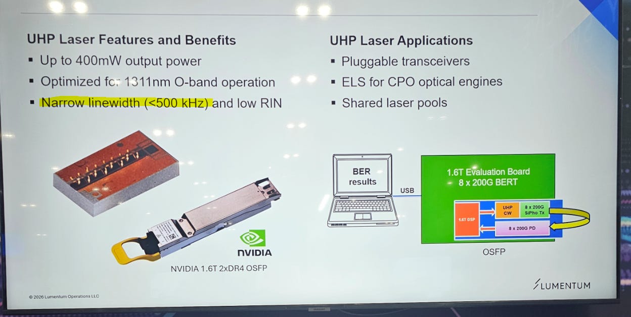
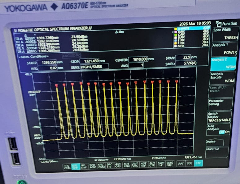
Wall-plug efficiency of ~13% at 30C. Very good. Should still be well above 10% industry target at 50C.
As a bonus, they even have a 800 mW DFB (at 50C!!!!) with 0.1 MHz linewidth.
SMSR is excellent indicating good quality of the grating and reduced mode-hop risk.
Asymmetry of the sidemodes is interesting.
Many keep asking me about what I think about various Lumentum competitors who also claim to have high-power laser solutions for CPO.
Coherent is the most popular, but AAOI and Furukawa also getting more interest.
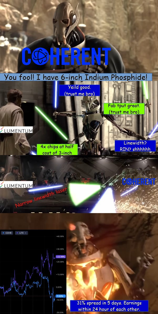
My answer is simple. Show me the linewidth.
LUMENTUM IS THE ONLY COMPANY WHO PUBLICLY DISCLOSES THEIR LINEWIDTH. GO ASK THEIR COMPETITORS WHAT THEIR LINEWIDTH IS. NONE WILL ANSWER YOU. THERE IS A REASON FOR THIS.

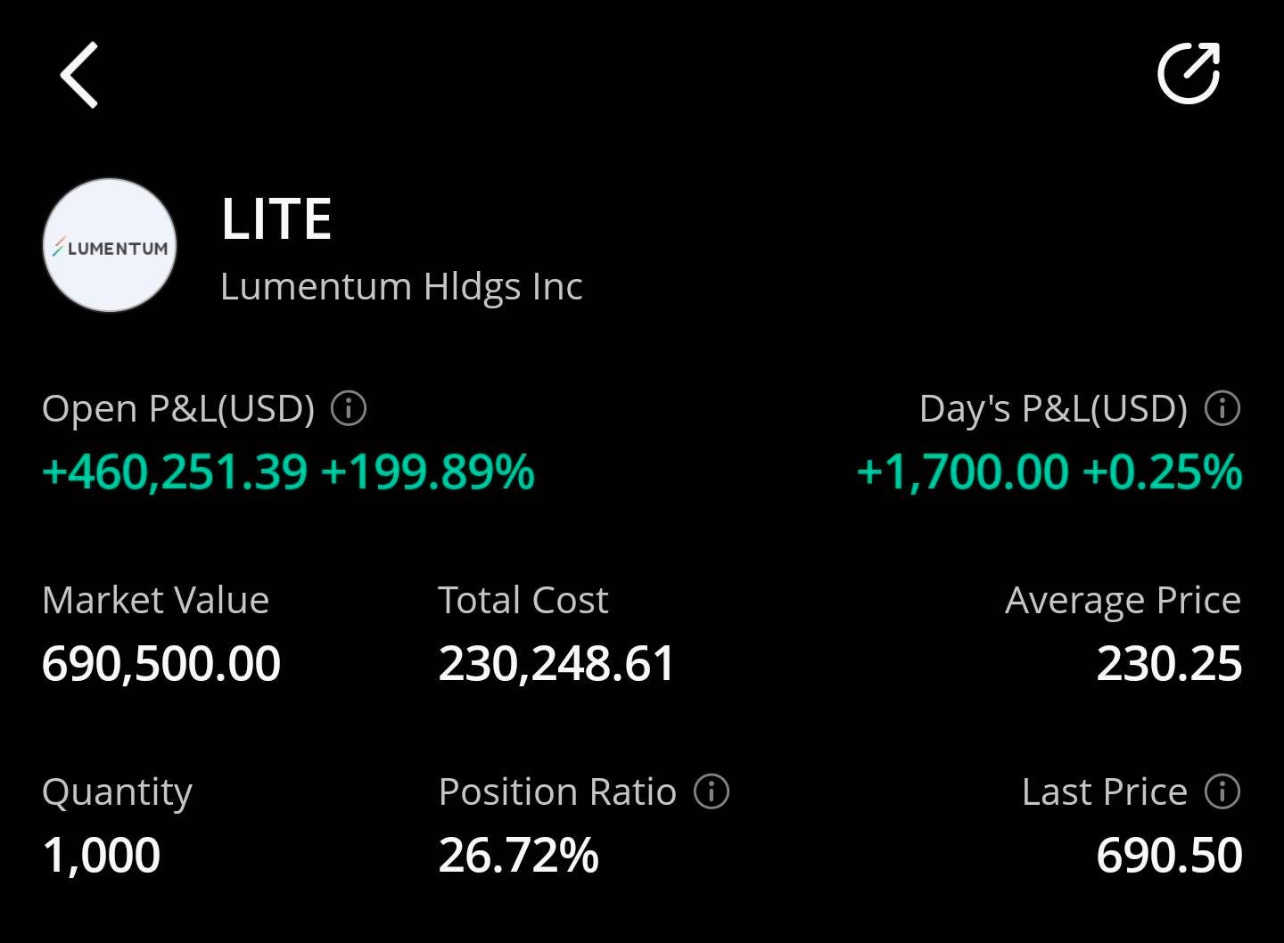
I’m not fucking selling. Lumentum is comically cheap if you understand the deep engineering moat they have and insane capacity plans for these ultra-high power lasers.
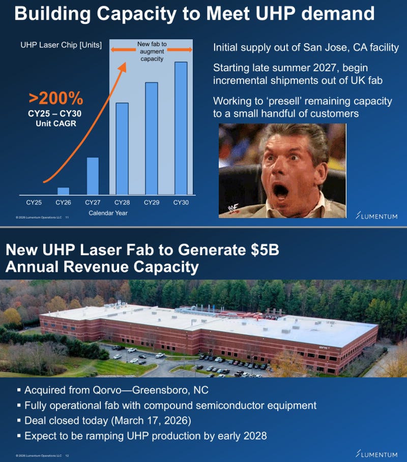
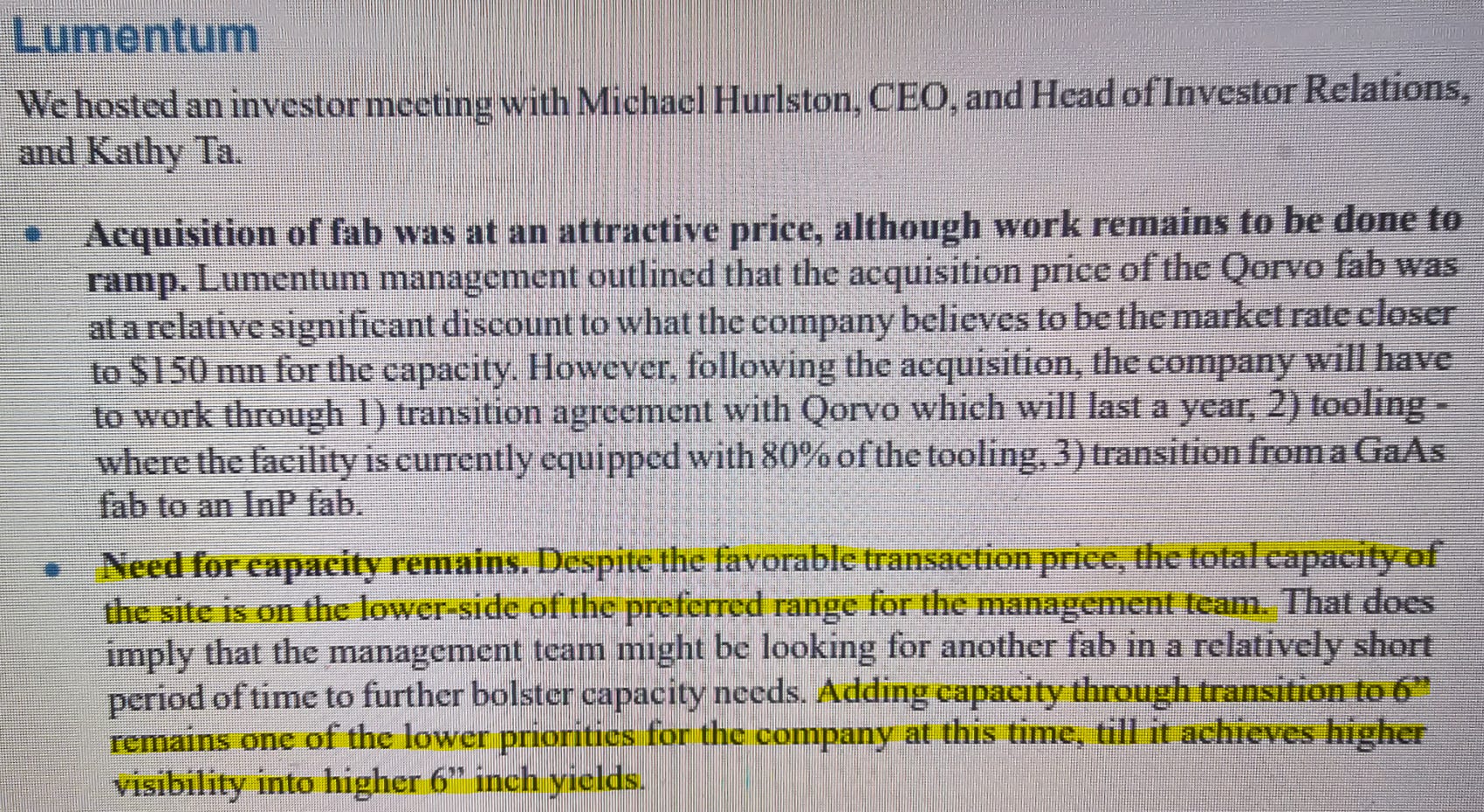
Lumentum and Coherent both got $2B investments each from Nvidia on March 2nd, 2026.
In under 3 weeks, Lumentum bought a huge fab to ramp production.
What has Coherent done with their Jensen bux?
Could it be that linewidth is a critical performance specification that only Lumentum discloses because everyone else linewidth is bad?
I want to really hammer this point home for all the spreadsheet enthusiasts out there who don’t understand shit about communications systems engineering.
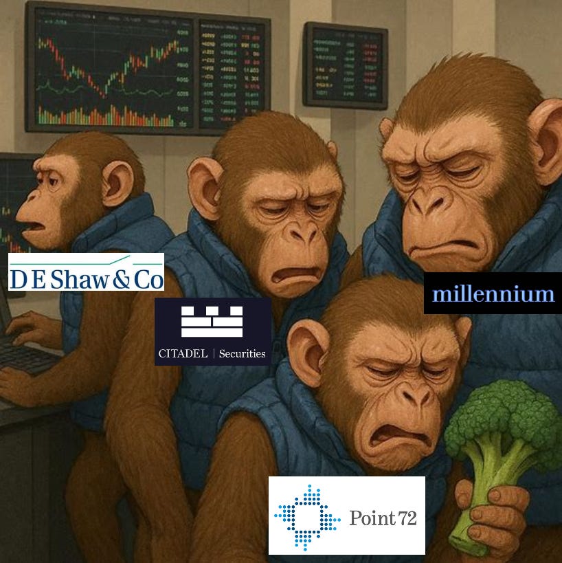
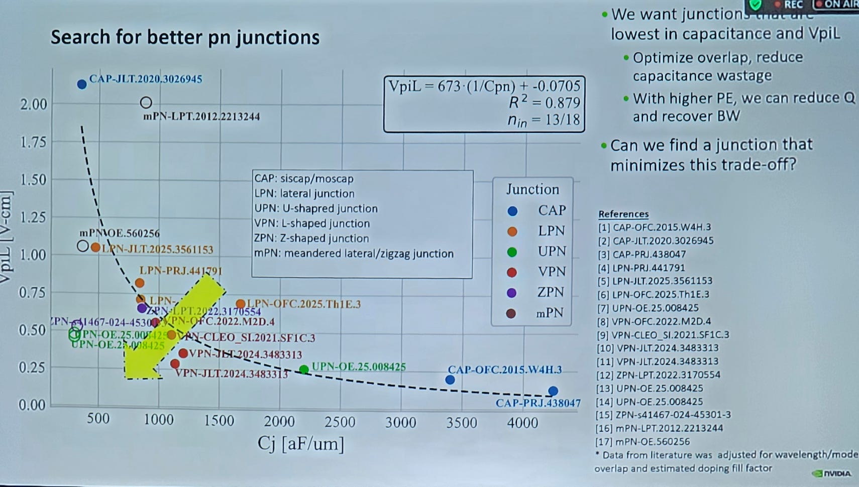
Here is a public research paper you can find in < 10 minutes of searching on Google Scholar. Pay attention. Eat your fucking broccoli, pod monkeys.
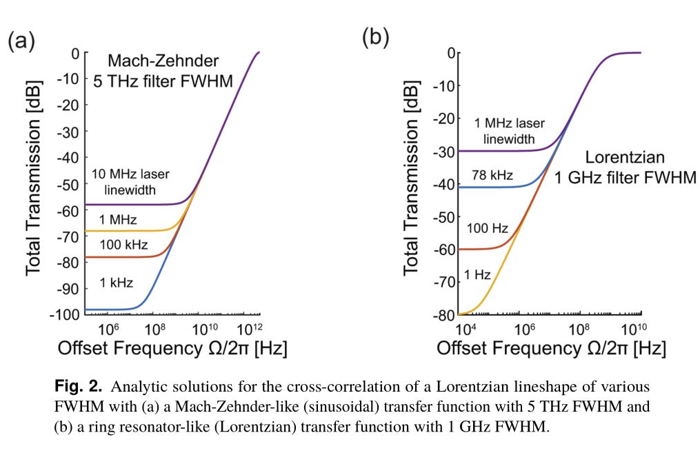
Ring modulators are much more sensitive to linewidth than MZI modulators.
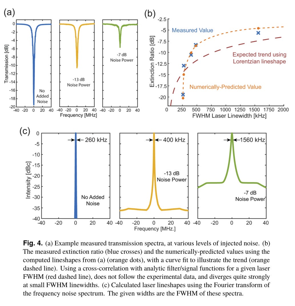
And by sensitive, I mean the extinction ratio is murdered by higher linewidth.
There is a massive structural shift where ring modulators are being mass adopted by everyone (except Celestial/Marvell) involved in CPO.
Historically, narrow laser linewidth was needed for coherent (16QAM, 64QAM) modulation of long-distance links such as ZR, not datacom.
With the mass adoption of ring modulators, led by Nvidia, linewidth has suddenly become much more important for a MUCH LARGER MARKET (DATACOM) THAT IS RAPIDLY EXPANDING (CPO).
There is no viable pure-play competitor to Lumentum. Broadcom has an excellent internal laser department but the stock is obviously not a pure-play to narrow-linewidth ultra-high-power CPO lasers.
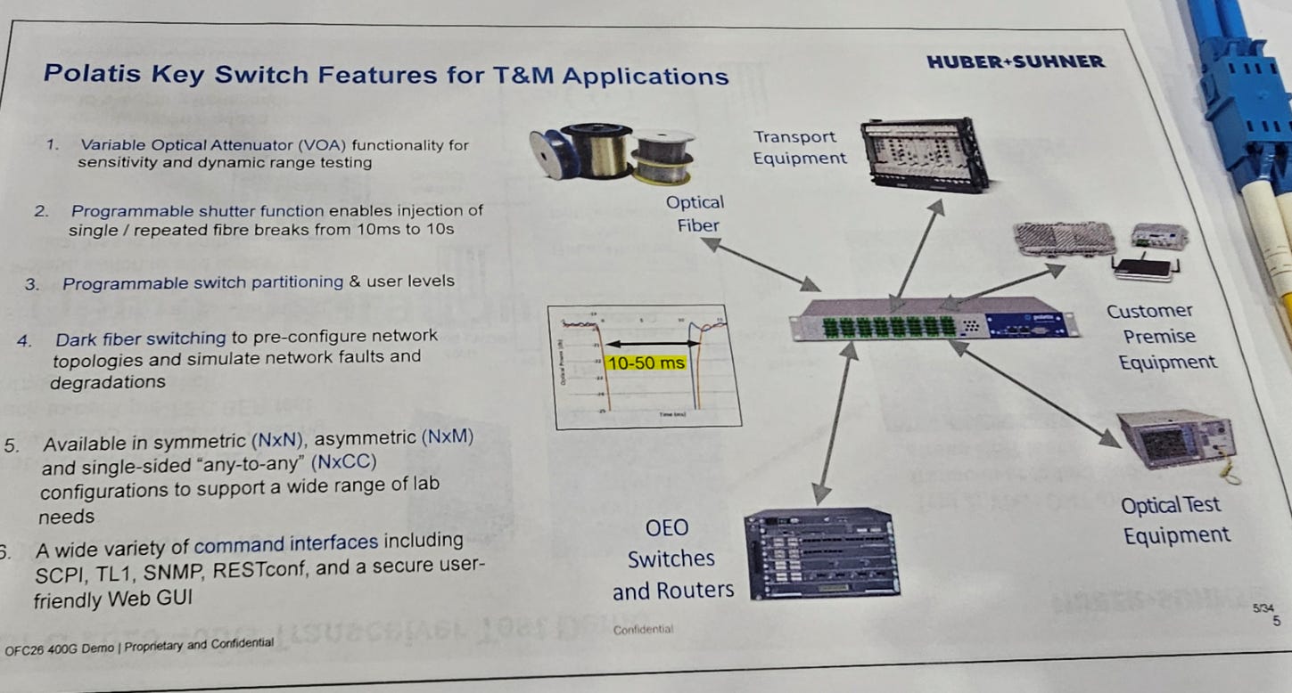
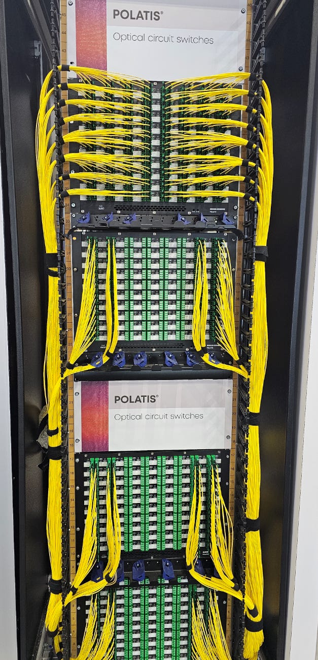
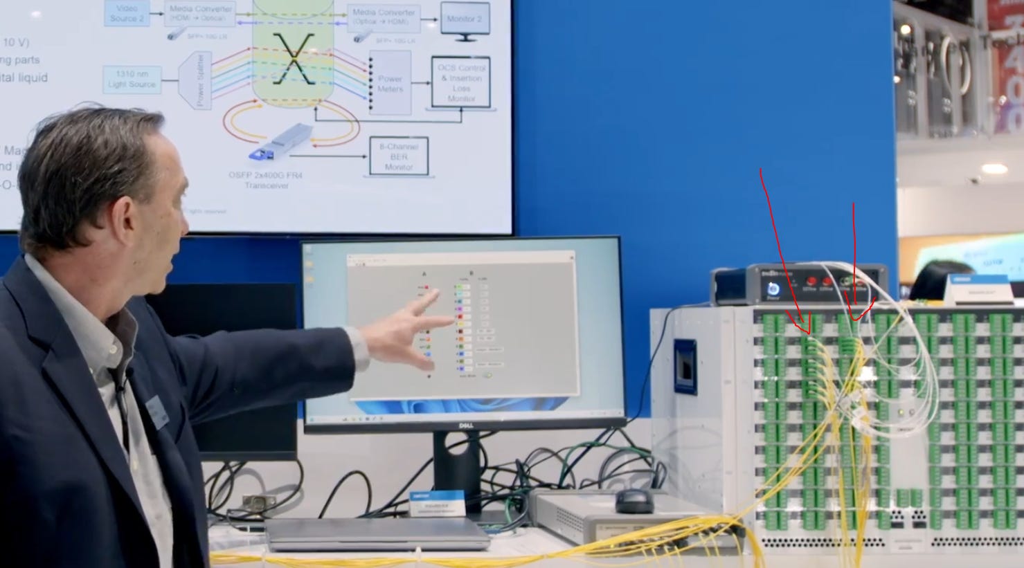
[1.d] Huber Schuner OCS
Over the past few months, several people have pinged me about the Huber Schuner OCS and I sort of gave a lazy response because was busy with other things.
Ran into this at their booth and… there might be something here.
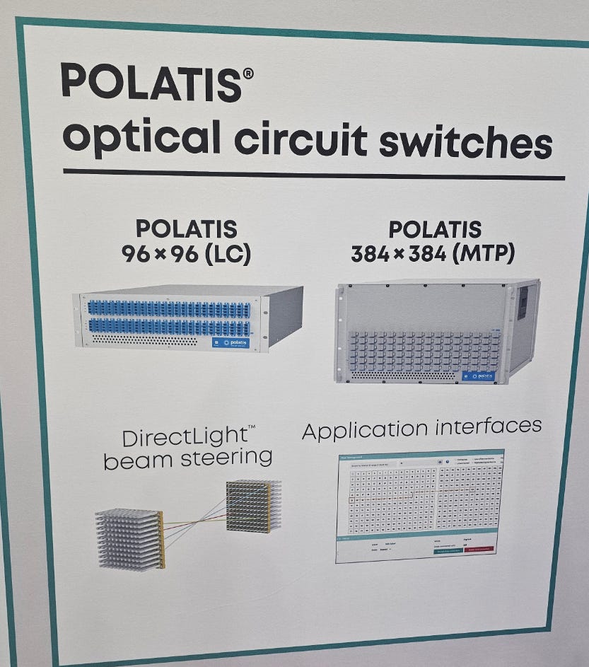
There are three broad categories of OCS.
MEMS (Lumentum)
Piezoelectric (Huber Schuner)
Liquid Crystal (Coherent)
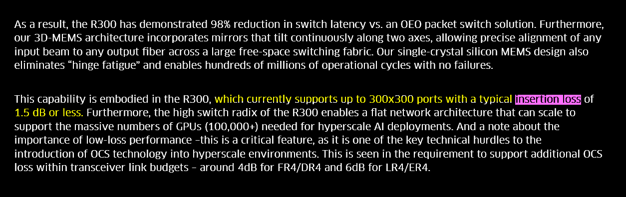
MEMS/Lumentum is winning by a wide margin because it is overall the best, particularly in terms of insertion loss.
(how much light you lose going through the switch)
Coherent loves to say how their OCS is differentiated from MEMS. No moving parts! More reliable! More scalable!
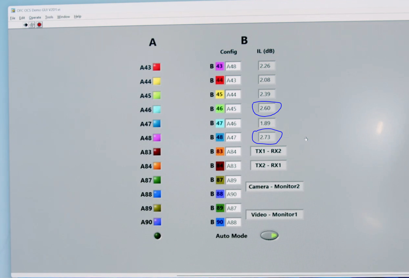
It’s differentiated by being bad. Very high insertion loss between ports that are right next to each other. Surprising lack of uniformity as well.
Spoke with a Huber Schuner employee and allegedly their OCS insertion loss is 1.5-2 dB depending on the size of the switch.
For comparison, here is Lumentum’s public claims on their MEMS OCS insertion loss.
https://www.lumentum.com/en/blog/optical-circuit-switches-in-ai-hyperscale-data-centers
Lots of people asking me about Lumentum vs Coherent OCS.
Maybe stop thinking about Coherent and give Huber Schuner a look.
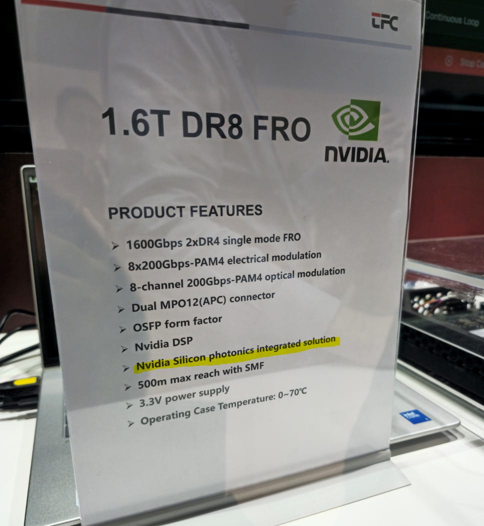
[1.e] Nvidia Super Overkill Transceiver
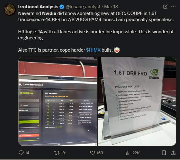
At the TFC booth (everyone laugh at the Himax bulls), Nvidia showed three versions of their 1.6T transceiver platform. All of them use the internal Nvidia DSP. Another L for Marvell lmao.
First we have the regular (fully re-timed) version.
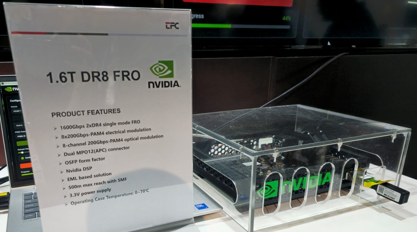
~15 pj/bit, excellent loopback BER.
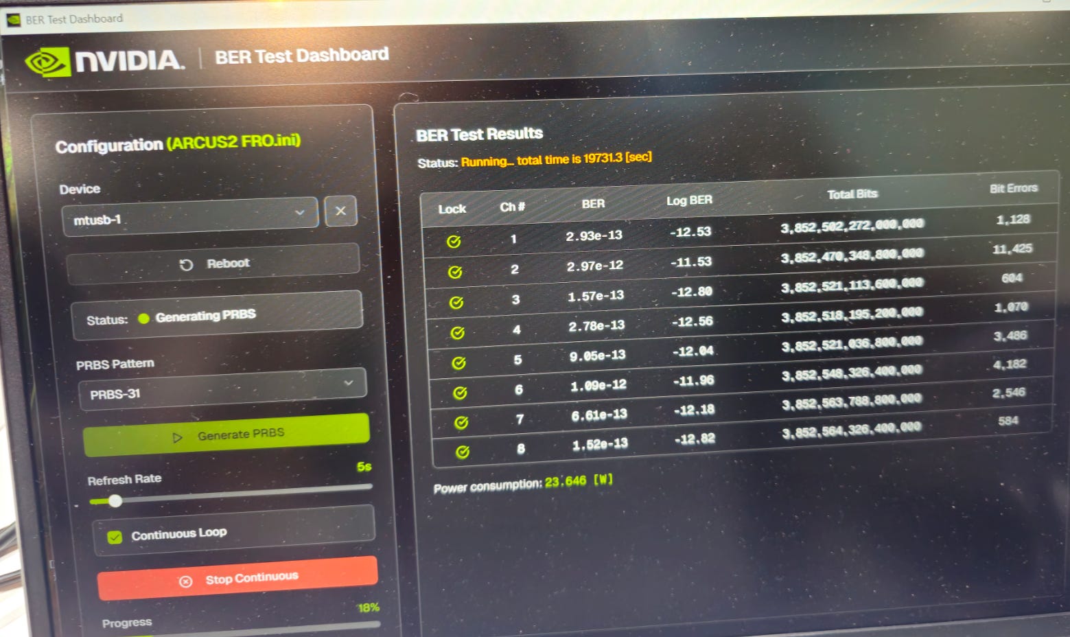
Then the LRO/TRO (half DSP) version.
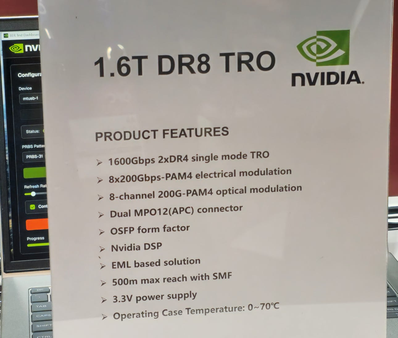
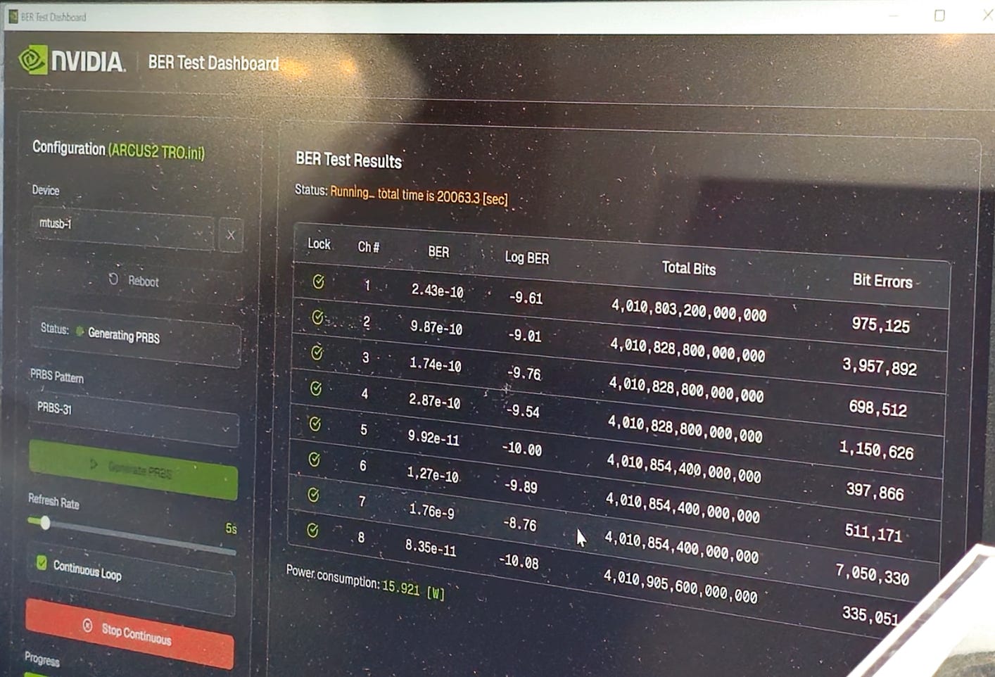
~10 pj/bit, good loopback BER.
And now for the shocking sipho/COUPE version using ring modulators.
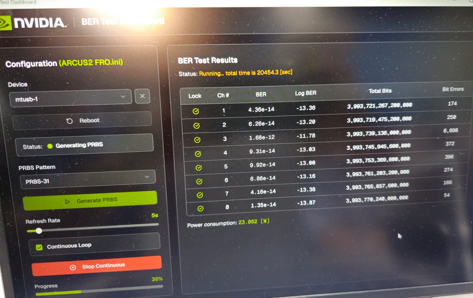
~14.5 pj/bit, incredible unheard-of performance.
Those of you who have not worked on this stuff cannot understand how insane these pre-FEC BER numbers are.
Getting 7/8 lanes to e-14 BER is insane. Even with extreme levels of cheating (cherry picking parts, slam die temp to 25C with large chiller) it is borderline impossible to hit this performance level.
Nvidia accomplished this using the power of hybrid bonding, TSMC COUPE, and ring modulators. Extreme co-design.
Obviously, these transceiver with COUPE inside is massive overkill and economically unviable. Way too expensive.
But still… extraordinarily impressive marketing demo. Taking shots at Broadcom lol.
[1.f] Broadcom/Meta CPO Reliability Update
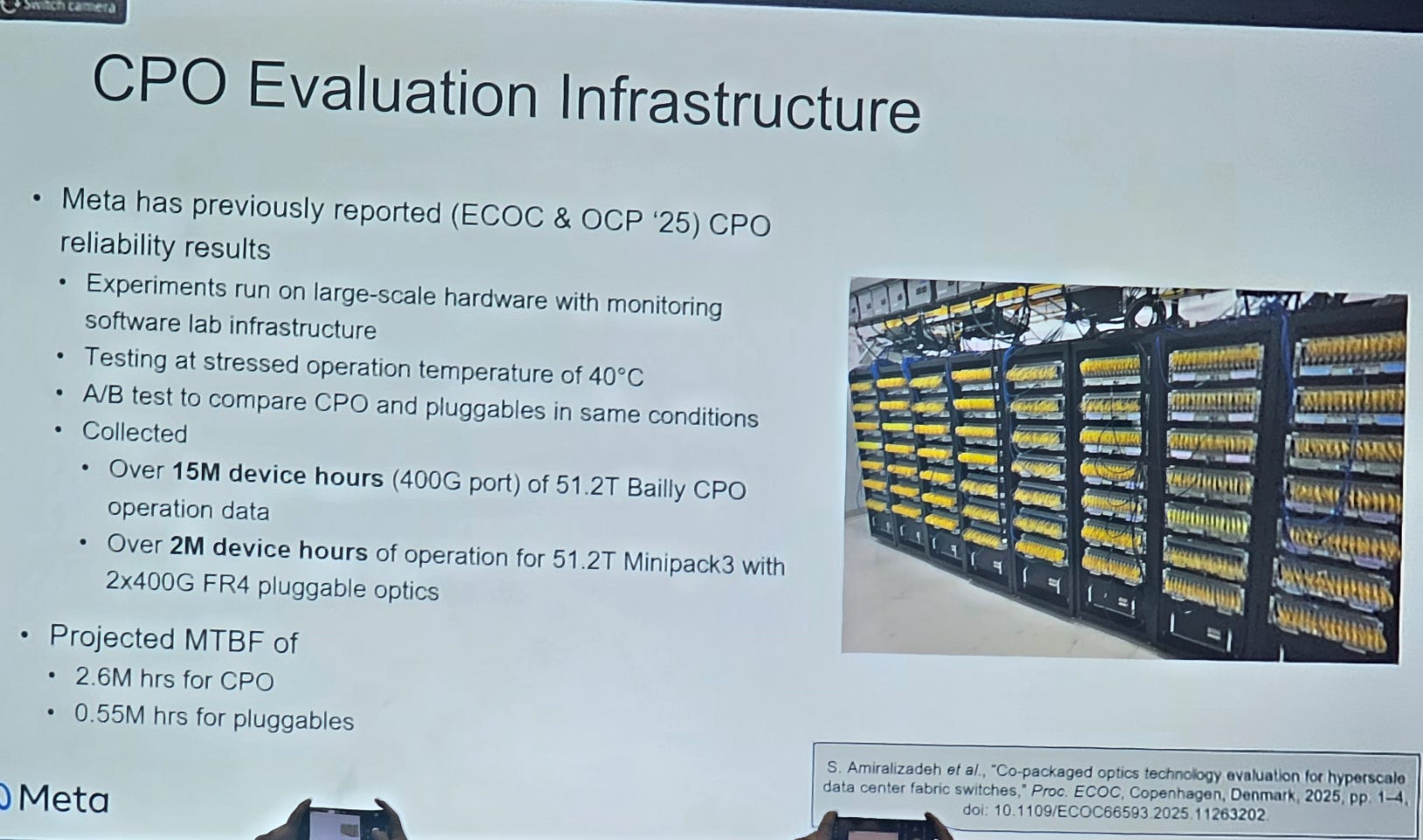
This is the old data they already showed.
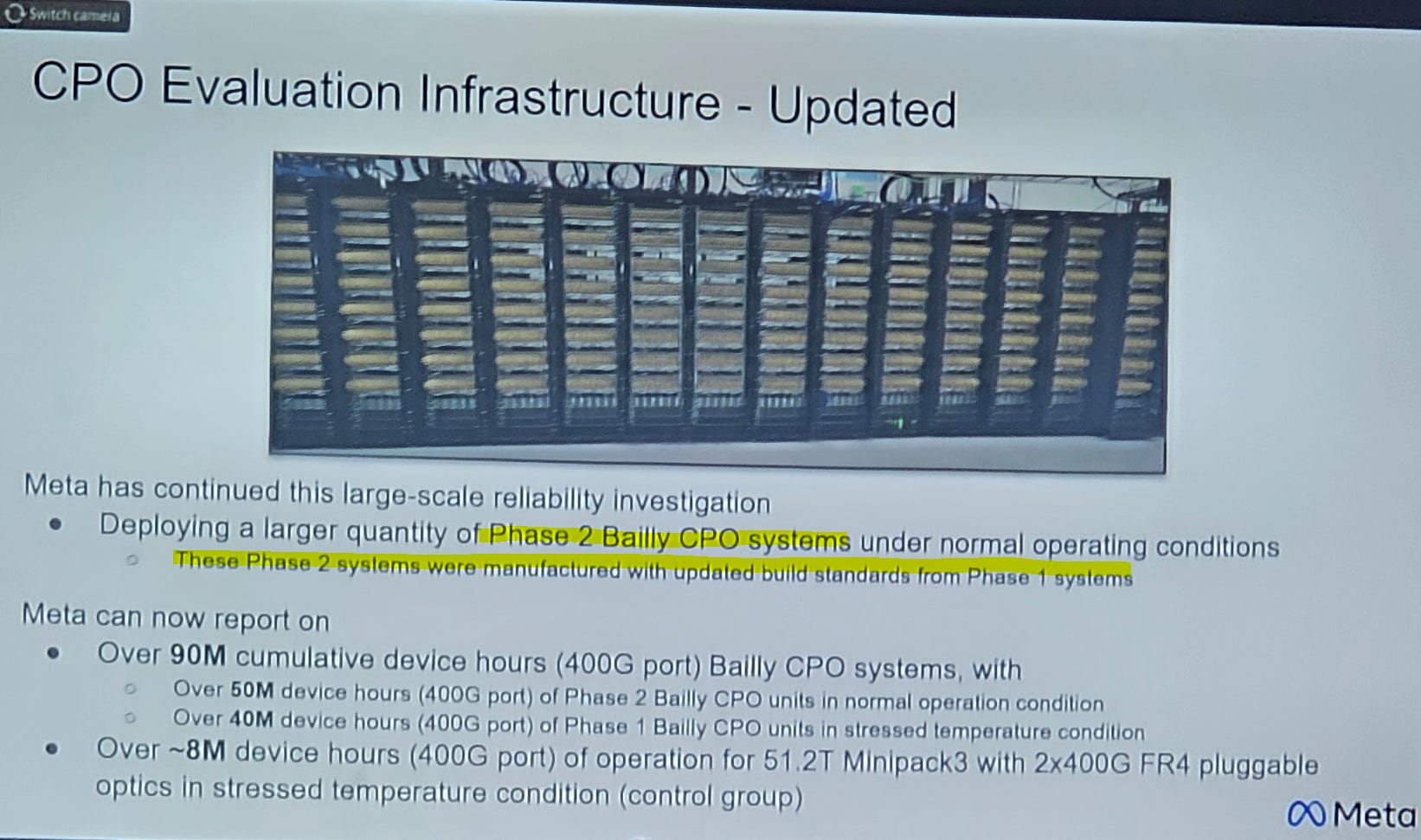
And here is the new data. They found some interesting hardware bugs. Will get to that shortly.
My blood pressure goes up every time some dumbass says CPO is less reliable than transceivers.
Motherfucker do you even know what FEC symbols are?
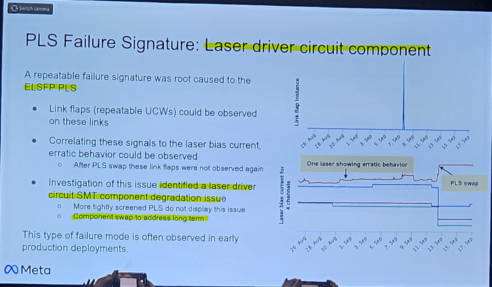
Amusingly, they had a minor problem with the ELSFP laser driver. Refused to comment on what “SMT component” had degradation issues but my guess is a capacitor. Probably switched some particular decap from tantalum to MLCC or vice-versa. Capacitors do not like heat.
This is why phase 2 CPO testing has “updated build standards”.
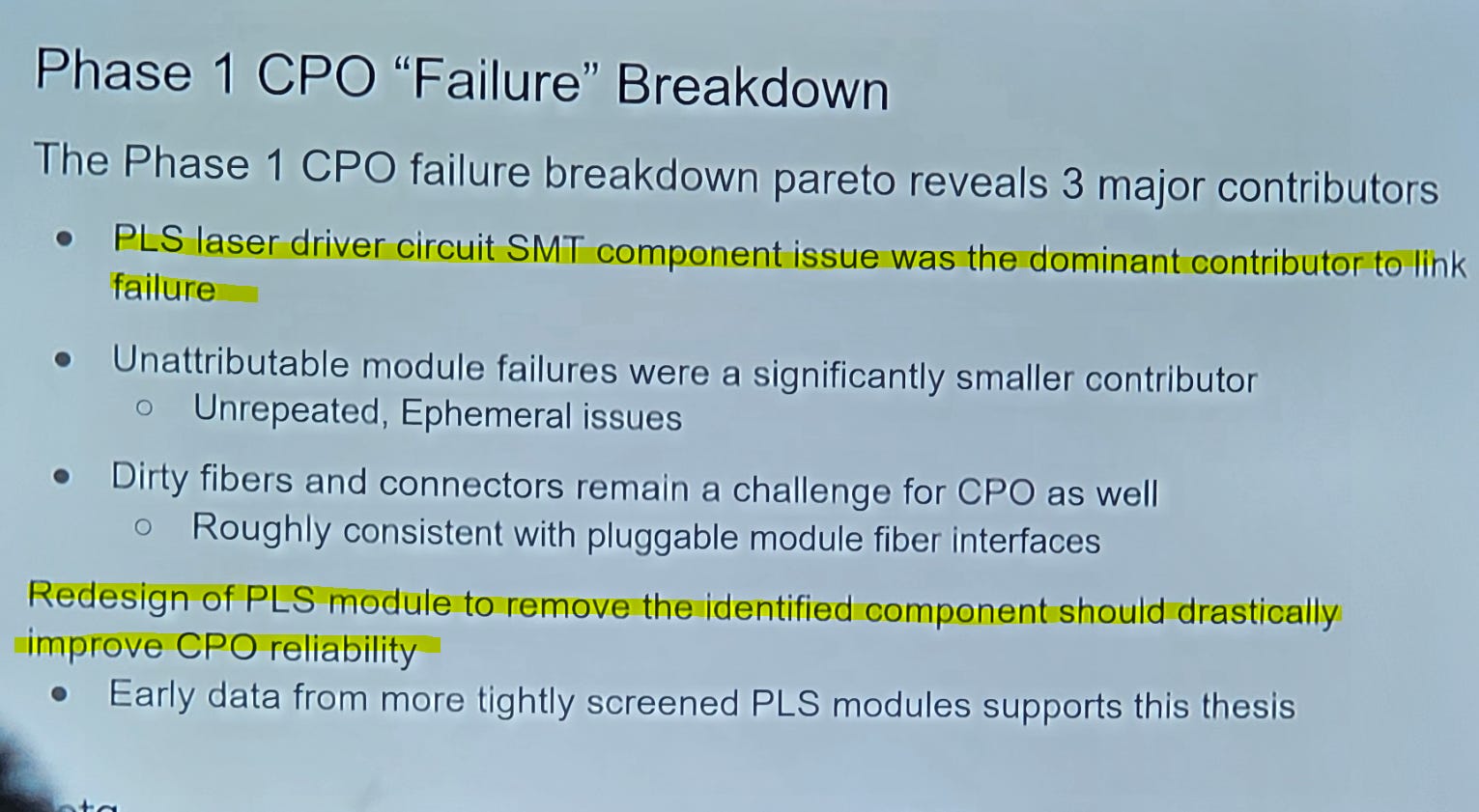
Finding these kinds of annoying problems well before mass-deployment in a production environment is exactly why Meta has gone to all this trouble.
Great stuff. Incredibly bullish SiPho CPO.
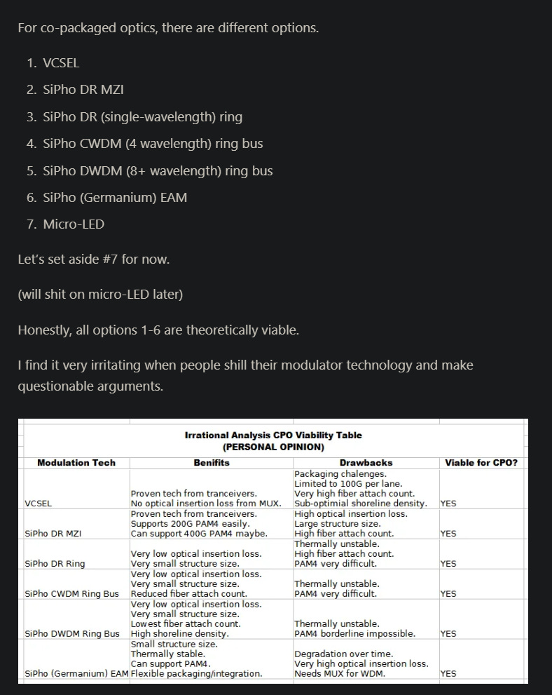
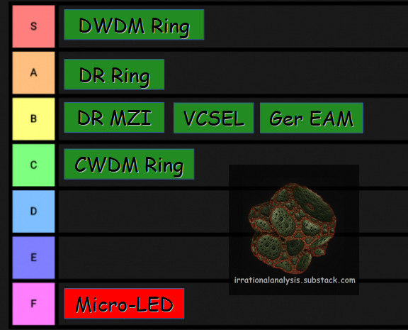
[1.g] I DESPISE MICRO-LED IN ALL FORMS
I am getting annoyed at the number of people pinging me on Micro-LED.
I HATE THEM ALL.
I HATE THE STUPID MICROSOFT PAPER.
I HATE EVERY SIGNEL MICRO-LED EFFORT EQUALLY WITH THE FIRE OF A THOUSAND SUNS.
Previously have covered the bullshit Microsoft paper here.
Going to snip the micro-LED section.
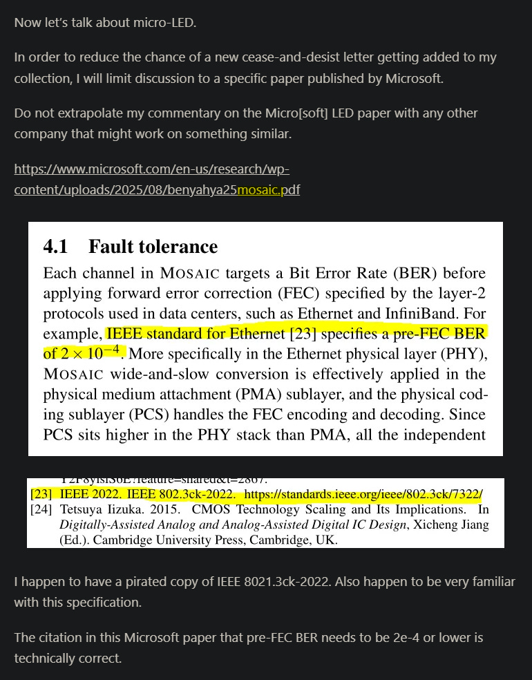
MICRO-LED WILL NEVER WORK.
ELECTRICAL CROSSTALK ALONE KILLS THIS IDIOTIC TECHNOLOGY.
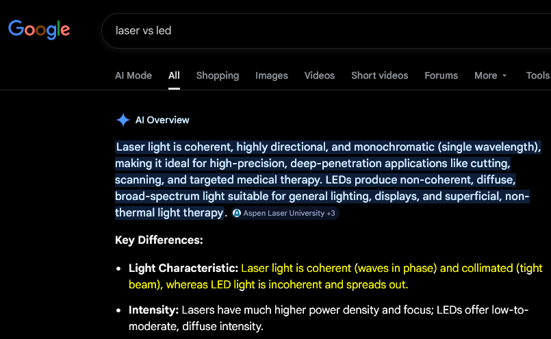
PHASE NOISE FROM THE INCOHERENT LIGHT OF AN LED MAKES THIS TECH EXTRA DEAD.
ALL THE MICRO-LED EFFORTS HAVE MASSIVE COPE ON WHAT BER IS ACTUALLY NEEDED FOR A VIABLE LINK. YOUR PJ/BIT NUMBERS DON’T COUNT FOR JACK SHIT IF YOU EXCLUDE THE MASSIVE POWER YOU HAVE TO BURN MASSIVE POWER ON SUPER HEAVY FEC AND VERY HIGH NUMBER OF LANES.

I am willing to give VCSEL NPO/CPO the benefit of the doubt. Don’t like it but it could work if done well.
Micro-LED is an ultra retarded version of VCSEL NPO/CPO.
[1.h] Optics Reach and Credo Dilemma

Optical fiber is wonderful. Incredibly low loss. Kinda the entire point of optics.
It takes great pain and suffering to get your data onto a fiber, but once you make it there, distance does not matter much.
In O-band (datacom standard band), there is effectively zero practical difference between 1-meter, 10-meter, and 30-meter reach.
Arguably, even up to 100-meter is the same but chromatic dispersion might have a small effect so trying to hedge a bit here.
Credo operates in a niche of 3-7 meter. This niche dies as advanced optics such as LPO, XPO, NPO, and CPO proliferate.
You could argue that Credo has a great optical DSP and are trying to diversify.
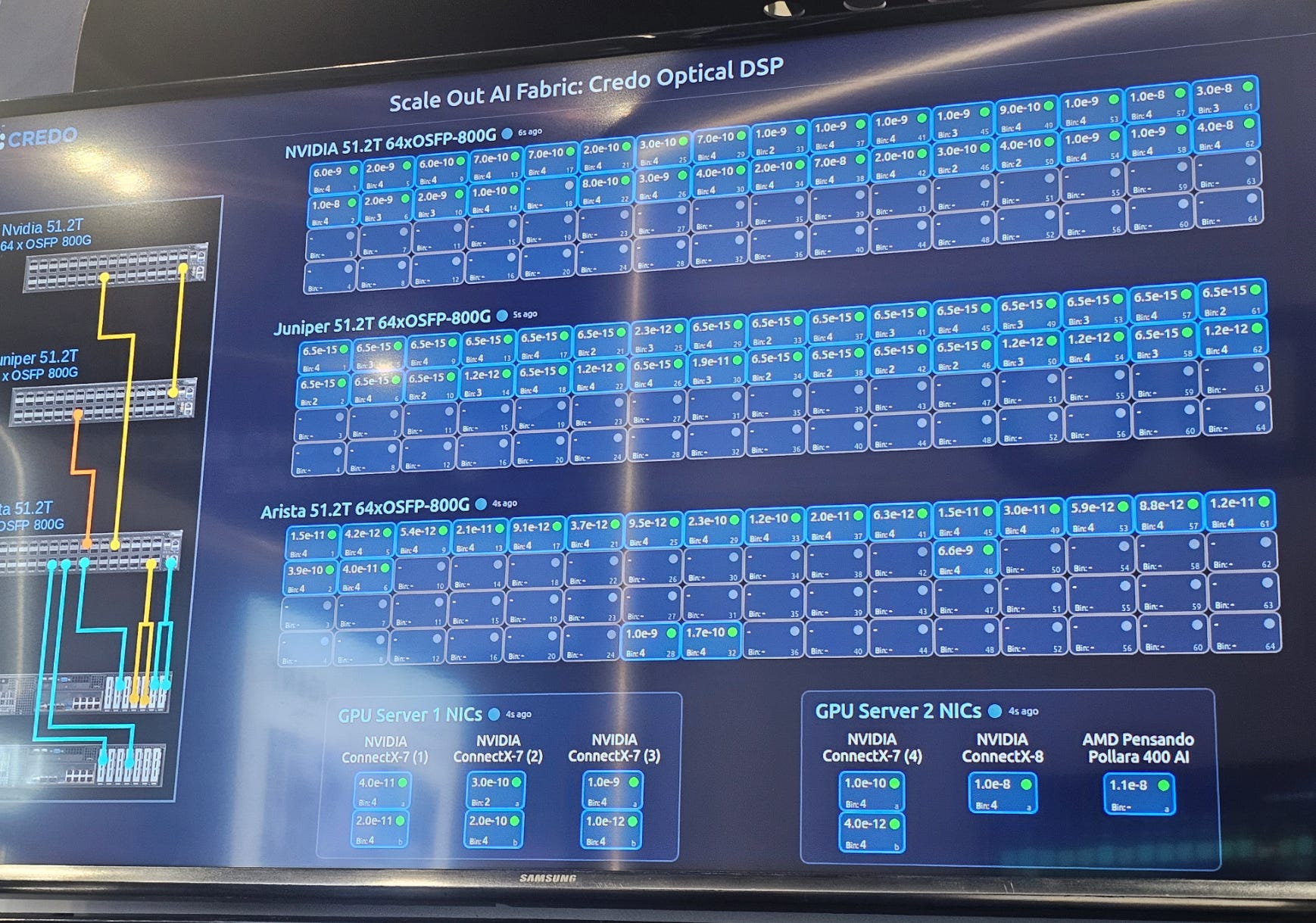
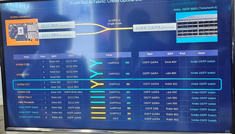
They had an extremely impressive interopt demo. Amusingly, this is not bullish Credo because they are entering a shrinking market with questionable terminal value. Credo optical DSP being really good is hyper-bearish Marvell, neutral Credo lol.
Also I despise micro-LED in all forms. Go read that section for the takedown.
[1.i] Marvell Seems Panicked: Anti-DSP Jihad Response?
There is a jihad (holy war) against optical DSP.
We have the usual suspects (LPO, CPO, NPO) but now Arista has XPO too. Everyone fucking hates optical DSP. Everyone hates Marvell’s most important franchise.
What’s worse is the optical DSP market is getting lots of new entrants.
We going from Marvell 80%, Broadcom 20% to…
Broadcom much higher share.
Credo take significant share.
Cisco, Maxlinear, and a few others I am forgetting going from zero to something.
And the entire market is fleeing re-timed optical DSP systems anyway.
I’m not sure what Marvell is doing. They seem to be throwing everything at the wall and seeing what sticks. The only reason I am not screaming for everyone to short Marvell into oblivion is Celestial.
(I am short right now for hedging purposes… sorry Celestial friends…)
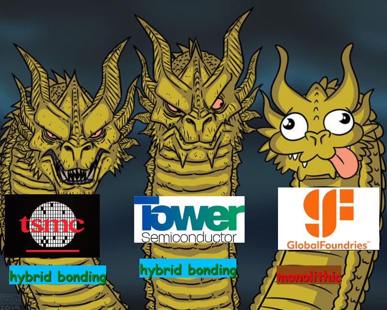
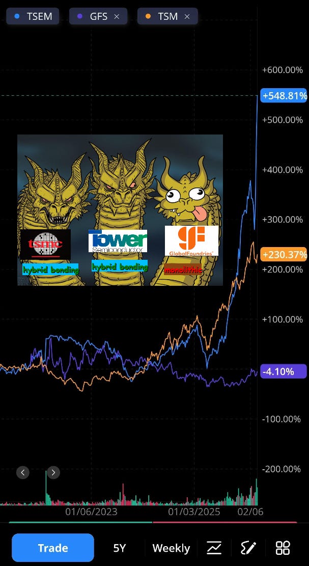
[1.j] Tower vs GloFo Sipho: NOT EVEN CLOSE
It is said that a picture is worth a thousand words.
I present to you my latest artwork.
Quick history detour.
A long time ago (5-10 years ago), it was thought that the best way to integrate electronics and photonics would be using a monolithic approach.
You see, photonics modulators need (in general) very high voltage swing. Around 2-5 volt pk-pk. Unfortunately, SerDes is typically around 400-800 mV, with a peak of 1200 mV in rare corner cases. (this varies based on standard and process node)
So you need some electronics to boost the signal before the photonics, but you don’t want to eat reflections or other channel impairments from packaging.
Thus, GloFo created the monolithic “fusion” node.
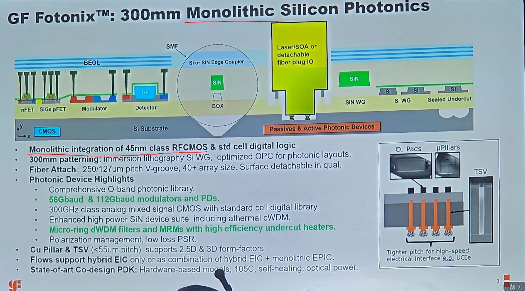
Imagine a standalone SiPho node and standalone electronics node each have ~30-60 process layers.
The GloFo fusion node has 100-150 layers. Amusingly, the cycle time is over 6 months (similar to 3nm-class nodes) even though the structures are 45nm-class and would usually take 2-3 months to fab.
I talk to many engineers from dayjobs and through this newsletter. There is always a spread of opinions. Even topics with extreme consensus have 5% of people taking the other side.
Except for GloFo fusion node.
Not a single person has ever said something nice to me about this monolithic PIC+EIC node. ZERO. Universally derided.
So many problems. Thermal crosstalk. Electrical crosstalk. Low-quality SiN performance. Painful cycle time and design rules. Poor bandwidth. Poor linearity. Can go on and on.
Ayar Labs and Lightmatter were both using GloFo fusion but have now aggressively pivoted to TSMC COUPE (hybrid bonded). Genuinely looking forward to seeing what those two can accomplish without the crazy process-node handicap they have been suffering through all these years.
There is only one chart you need to see to understand why GloFo fusion is so bad.
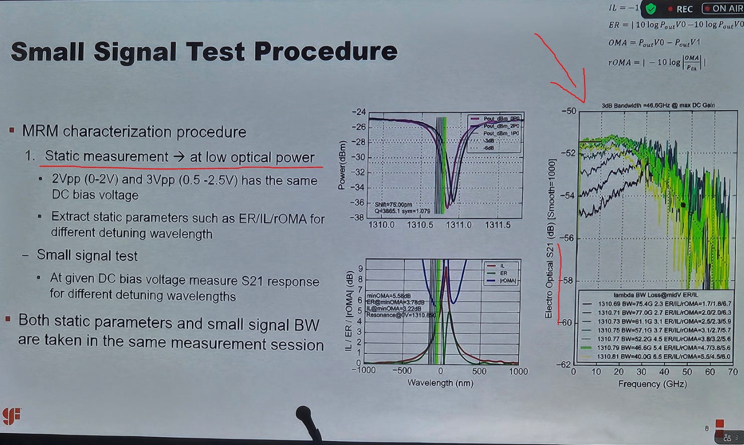
Let’s zoom in and make direct comparisons.
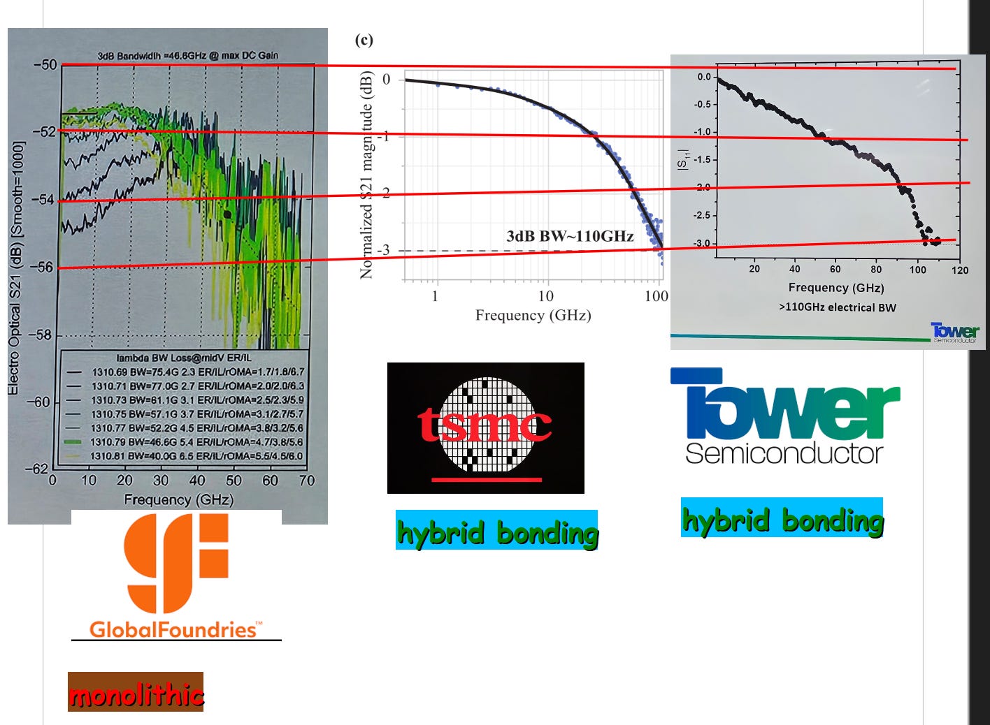
I made a poor attempt to scale the plots such that the y-axis is roughly similar.
As you can see, the (correct) hybrid-bonding approach delivers ~110 GHz of bandwidth while GloFo fusion only gives 40-75 GHz of bandwidth. Even then, the frequency response becomes super noisy after 30GHz.
(also for some reason GloFo did not normalize their data… whatever)
Those of you with the appropriate engineering background know what the charts and numbers mean. You will also notice Tower marketing screwed up and labeled their chart S_11 instead of S_21. This is a typo. Silly mistake. Let it go.
Those of you who don’t know what the fuck I am talking about… you can easily recognize that one of these charts is not like the other two and looks really ugly.
Global Foundries has made the wrong technology choice and are still refusing to pivot. Tower saw what TSMC did with COUPE and quickly brought their own (HYBRID BONDED) solution to market less than a year later.
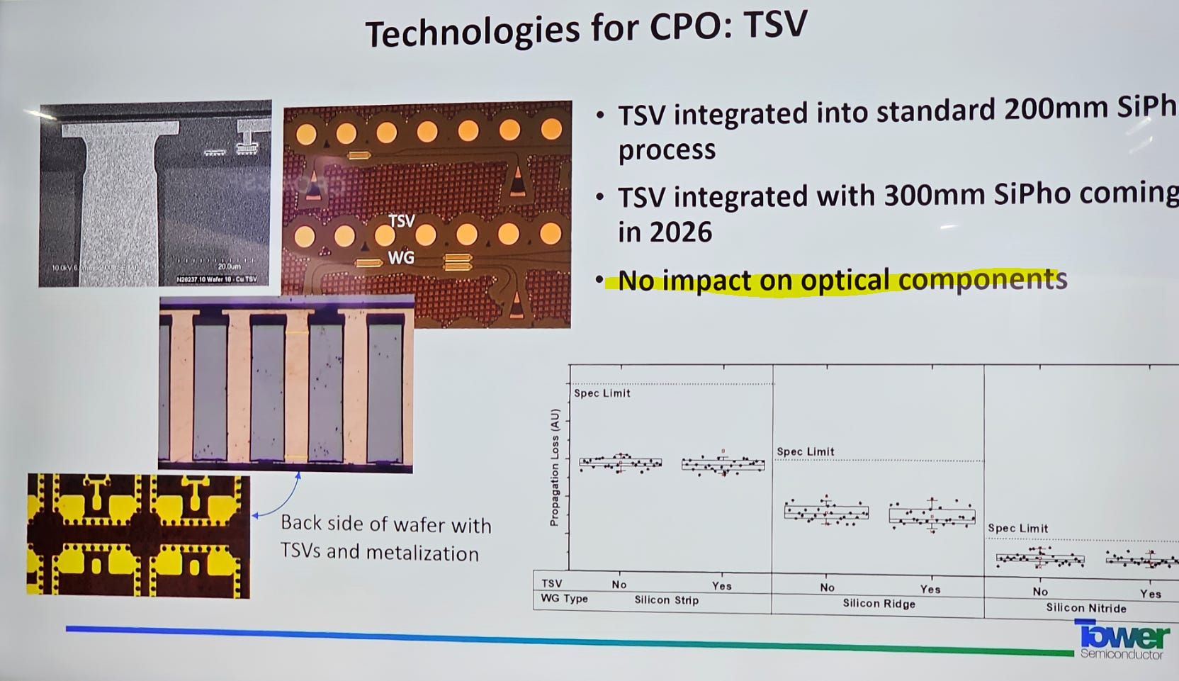
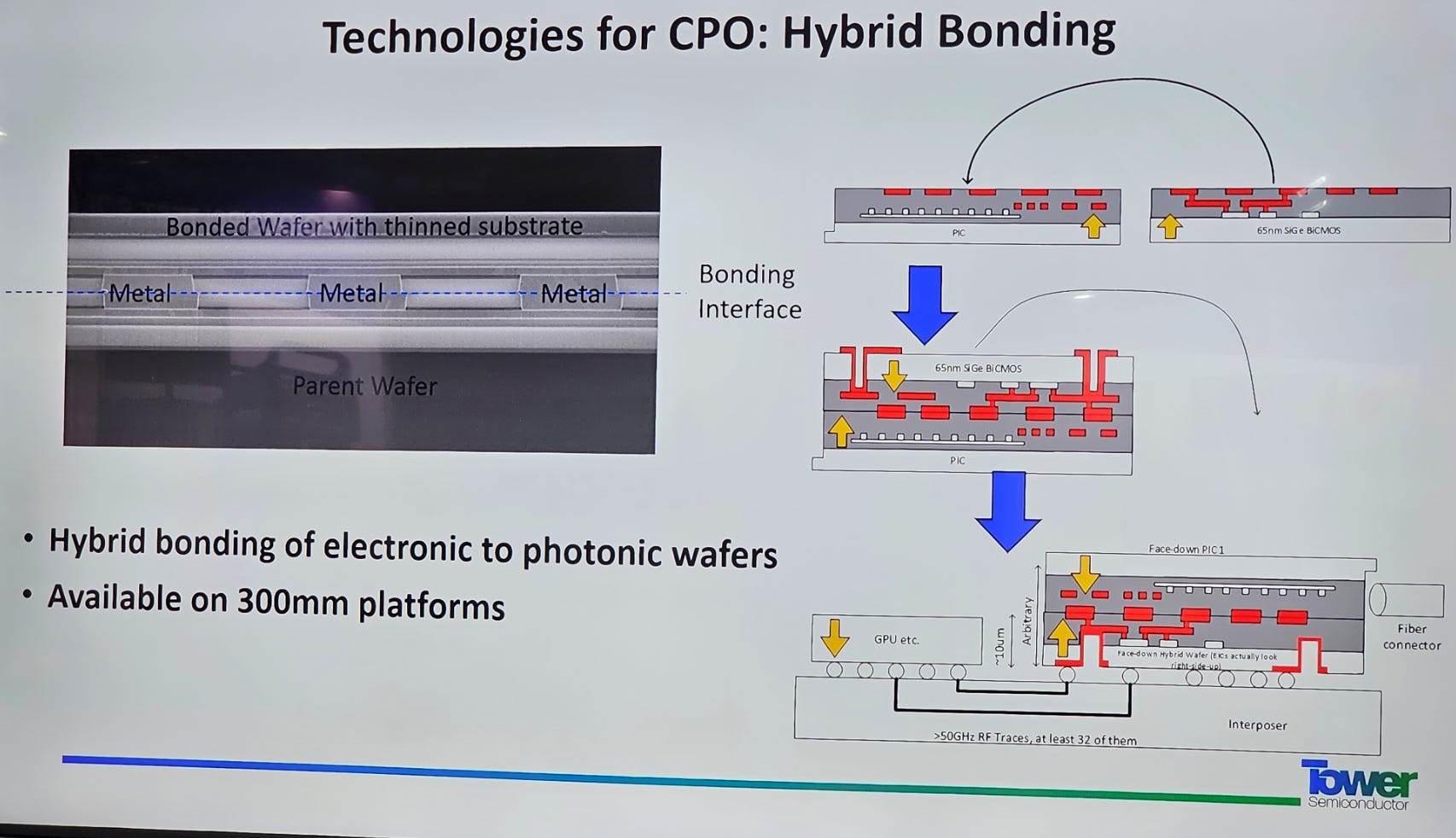
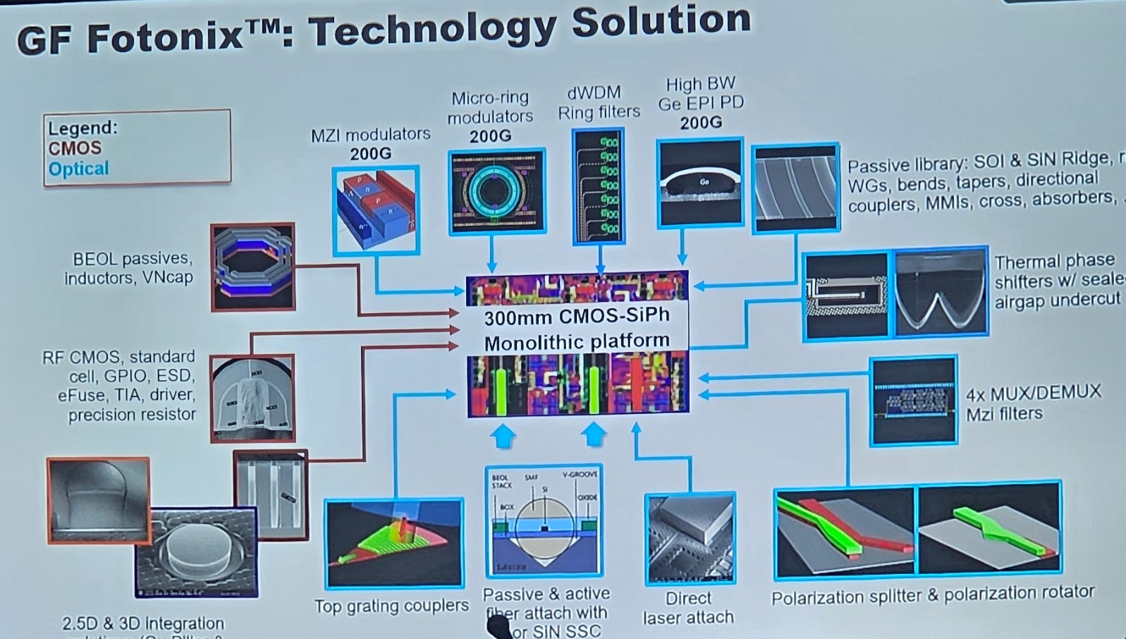
Tower also has several other nice features on their excellent SiPho platform.
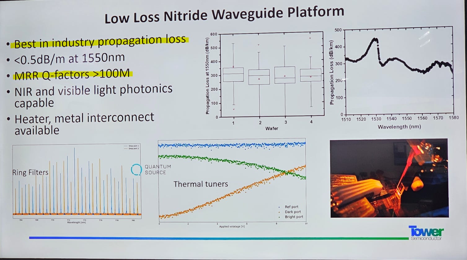
Worlds best silicon nitride.
InP hybrid integration via Openlight. (PDK abstracted!)
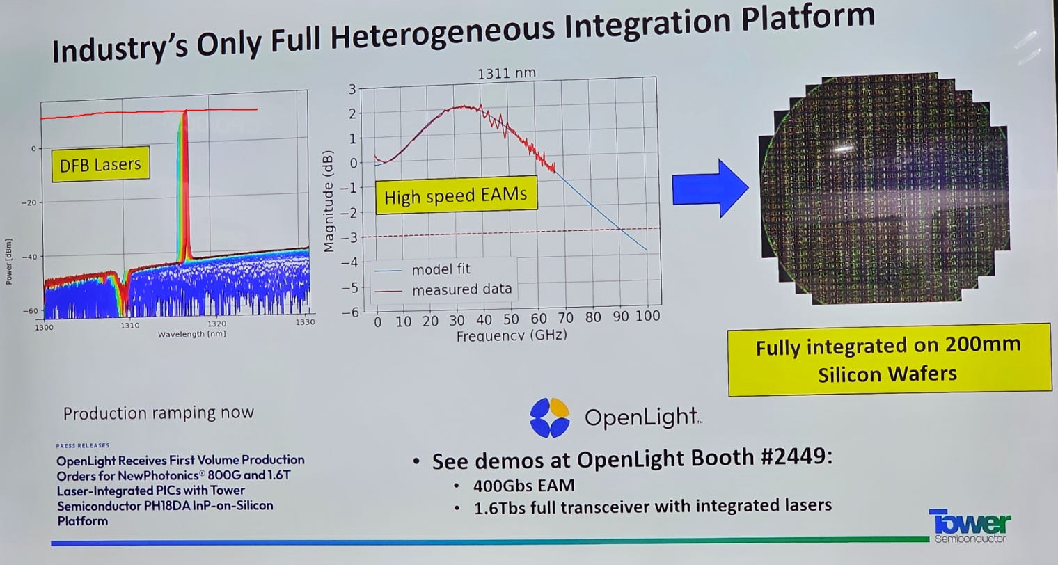
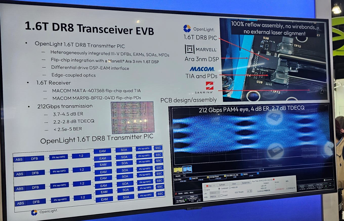
Up to ~ 11 dBm integrated DFB lasers, 20 mW (13 dBm) integrated SOA, and quite high quality EAM modulators as well. BEAUTIFUL.
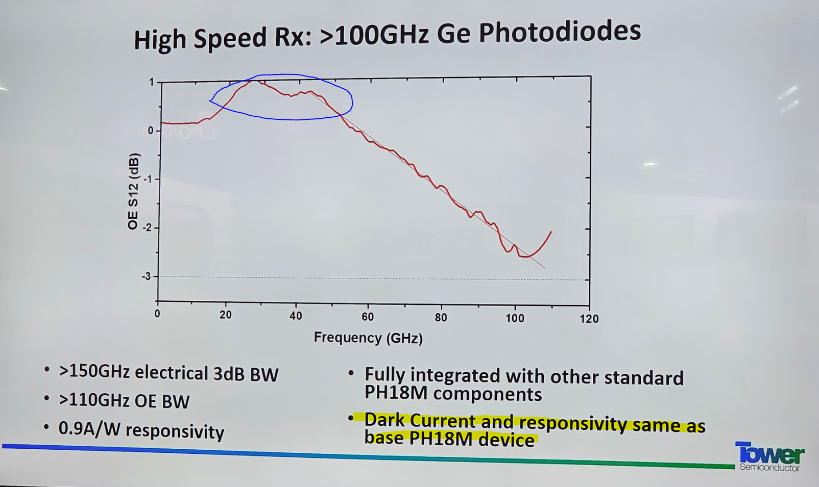
Great dark-current performance and PD bandwidth but the peaking between 20-50 GHz is a mild annoyance. Gotta nitpick this.
Also the ESD tolerance/reliability of Tower PDs has room for improvement.

In Russell we trust.
[1.k] Apology to Zephyr on Furukawa Laser
Ok so the Furukawa high-power laser is real. They had a live demo.
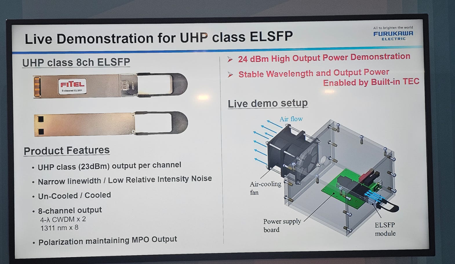
Claims to have good noise performance but I asked the guy what the RIN is and he gave a very evasive answer. Facial expression told me “fuck fuck dont answer this fuck”.
He did answer my question on if this is a normal DFB or a MOPA.
https://www.coherent.com/news/glossary/mopa-technology

There are two ways of making a high-power laser.
The normal way is to make big laser. This is difficult as you have to control noise very well. Only Lumentum knows how to do this at 400+ mW class.
The other way is to have a smaller laser (~100 mW) seed a SOA (semiconductor optical amplifier). Both elements are on the same InP chip. (monolithic)
MOPAs are nice because it is much easier to get good noise performance. The drawback is cost (larger InP chip) and mode-hop risk.
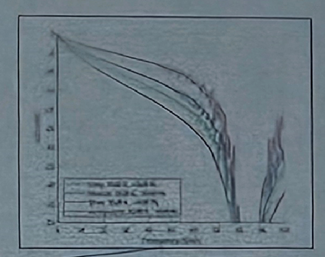
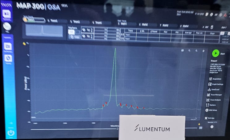
Here is a random chart that illustrates mode hops well.

Lasers like to jump around in frequency and power at specific drive currents and temperatures. MOPAs are much more prone to mode hops because of the cavity between the SOA and the seed DFB. Also much more prone to back-reflection.
It is impossible to know if this Furukawa laser has been sufficiently hardened against mode hops without detailed testing in a laboratory environment.
But… at least Furukawa has something.
Coherent is playing catch-up, trying to pivot to a MOPA for UHP laser market. Maybe Furukawa is worth a bid over this possible CPO laser upside.
[1.l] AAOI Booth
I stopped by the AAOI booth to see if their transceivers are legit and… looking good.
~e-12 pre-fec all lanes for 800G. Good.
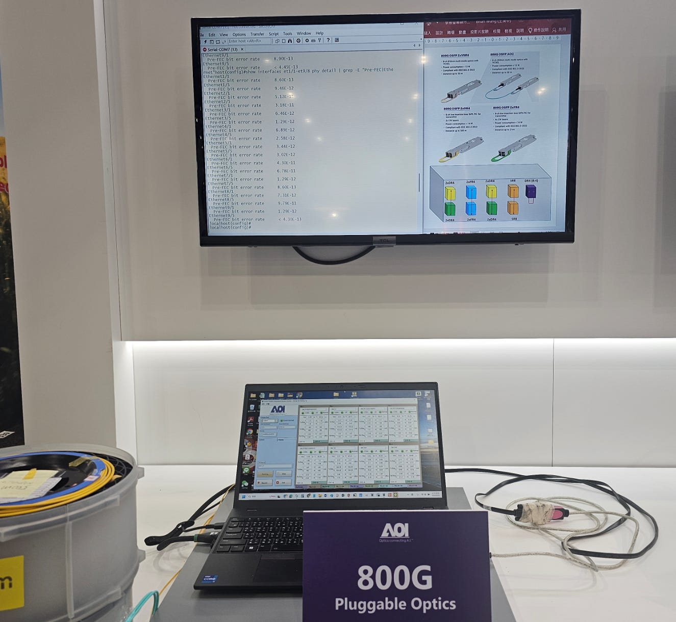
For 1.6T the performance is a touch lower than I would like but still decent.
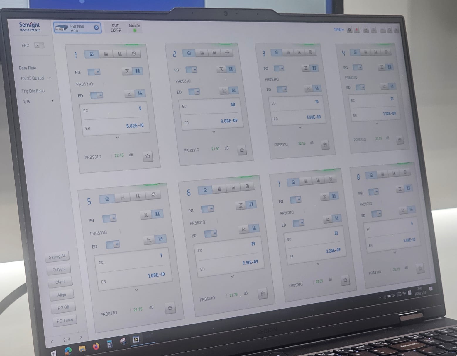
Until I realize the low BER lanes are actually RTLR/LRO.
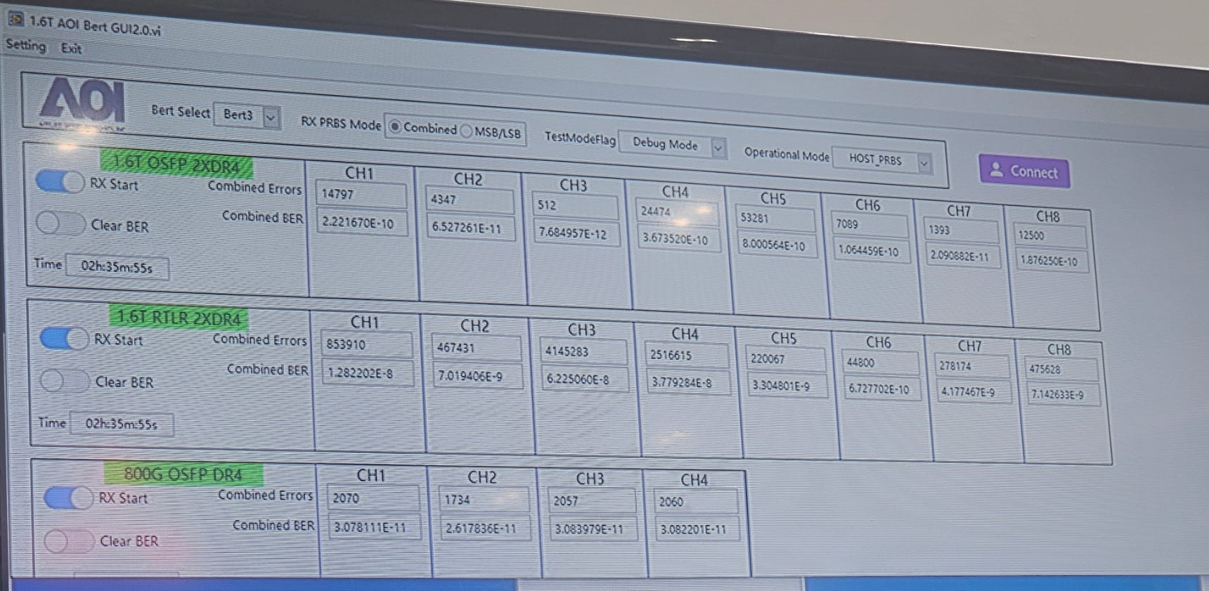
Yea this is pretty good. Test was running for over 2 hours so it’s not cheesed.
Also have some high power lasers for CPO but no info on linewidth or RIN. No noise performance == messa not interested.
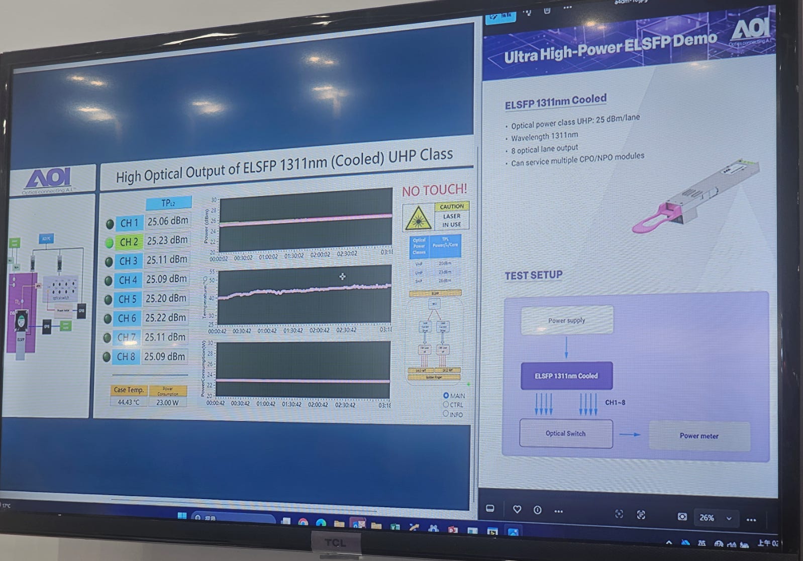
11% wall-plug efficiency probably at 30C TEC setpoint given case temp is 44.4C. A 15-ish C delta between case and TEC cold side temp seems reasonable.
So worse efficiency than Lumentum’s 13% at similar target TEC setpoint.
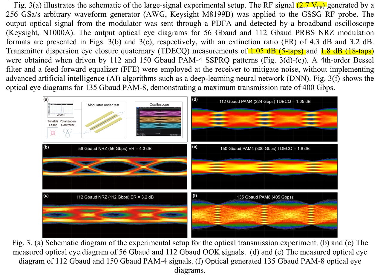
[1.m] 400G EML vs SiPho
Many have asked me about 400G situation for EML vs SiPho.
Some are SiPho bulls, others are EML bulls.
The answer is you should stop over-thinking things and everything goto the moon.
Yes, EML is much better at 400G than SiPho. So what? More of the 200G market will transition to SiPho and precious InP capacity will still be slammed by 400G EML and CPO/CW ultra-high-power lasers.

Some generations of speed (100G, 40G) are not popular. Honestly, 40G was dead on arrival.
800G, 1.6T, and 3.2T will all have wonderful lifecycles and explosive growth.
You think those 400G EML InP chips are small? No! Need way more laser power and modulator die size to hit SNR requirements at much higher baud rate.
Everything is fine finance friends. Stop trying to find excuses to be worried about your sipho or EML holdings.
Here is the excellent Coherent demo. They put a (almost) apples-to-apples comparison of EML vs SiPHo at 400G.
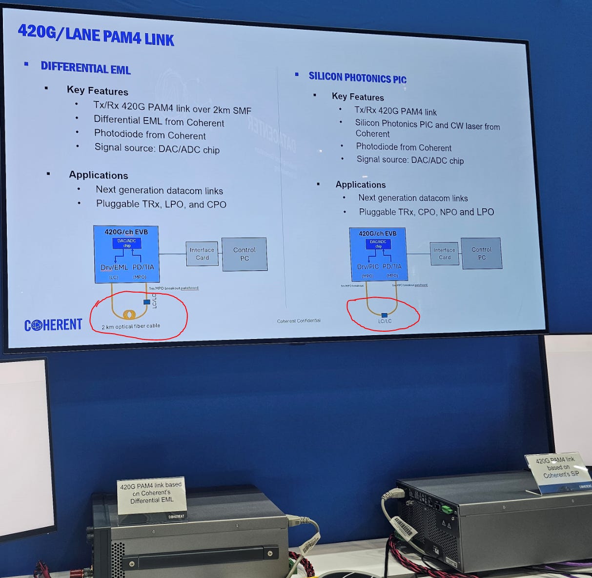
Notice that the EML demo has 2 km of fiber while the sipho demo has a short patch loopback.
That is a good 1-1.7 dB delta depending on the band!
Despite this favorable fudging to try and make sipho look good, we get drastically different histogram results.
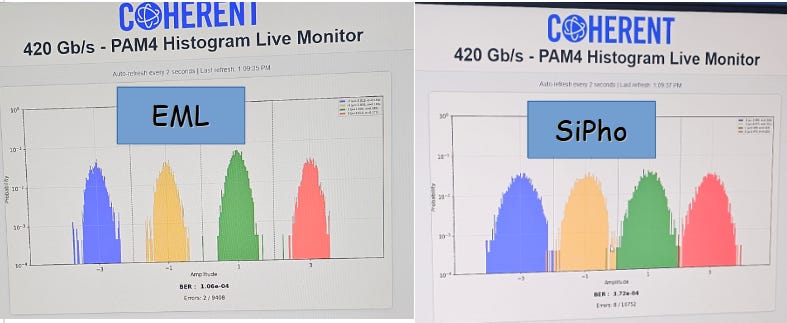
SiPho histogram is ass. Obvious bandwidth limitation.
EML clear winner at 400G and that is fine. Just means that 200G/lane products will get even more rapid SiPho adoption.
As an aside, 400G modulation is possible with rings and COUPE using clever co-design. So CPO 400G/lane is all good. Rejoice sipho bulls.
Here is Lumentum’s 400G EML demo.
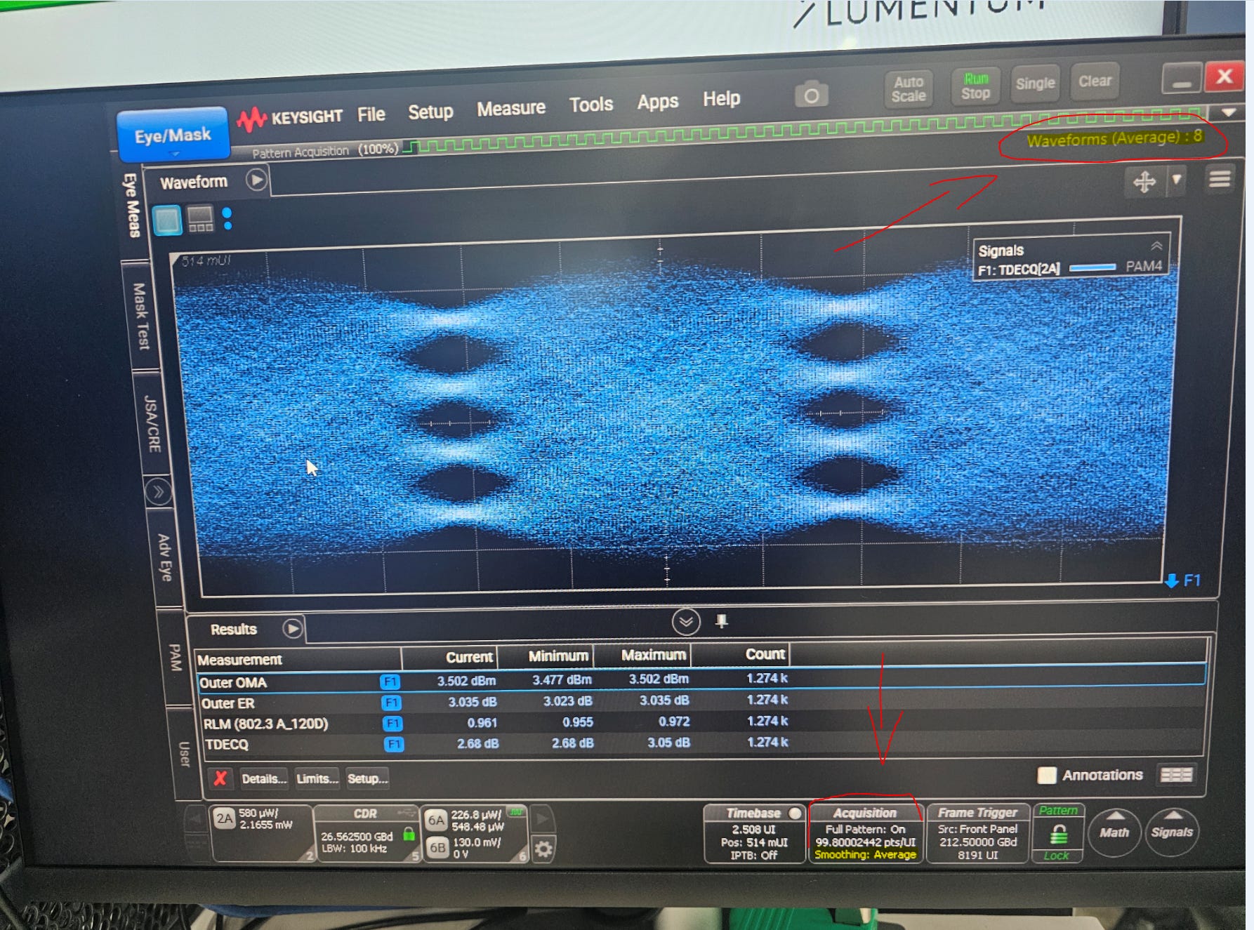
They used scope averaging. This is a big no-no. Called out Nvidia for using averaging in their ISSCC 2026 presentation and gona call out Lumentum here.
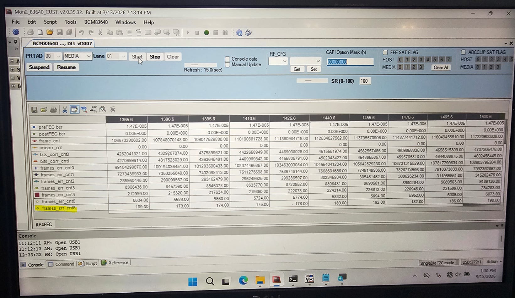
Annoying they stopped the FEC tail at symbol 6. My guess (from looking at many FEC tails) is they are well past symbol 8. Probably some hits on symbol 10/11.
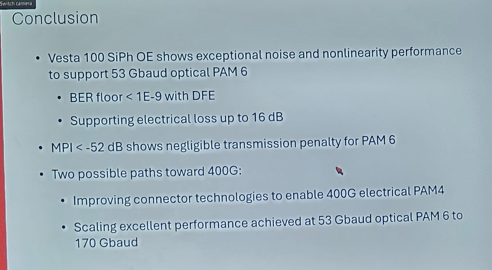
[1.n] Impressive Ciena Presentation
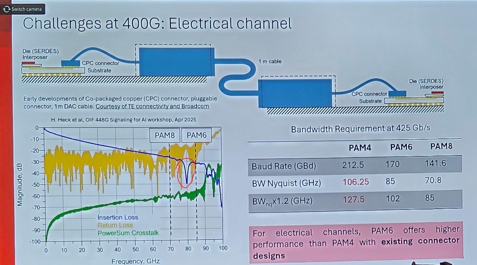
I would argue that the nasty loss at 80-85GHz means PAM8 is the best but whatever.
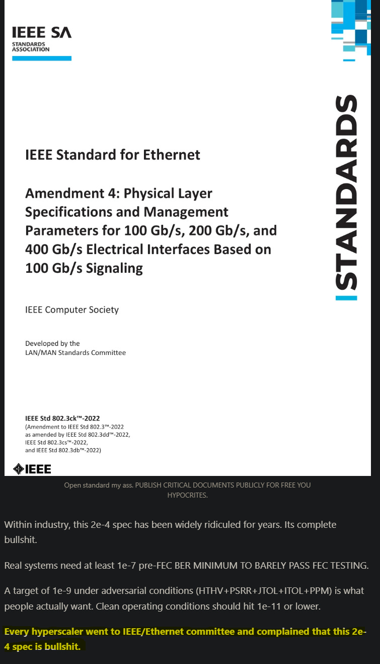
IMO min requirement should be 1e-7.
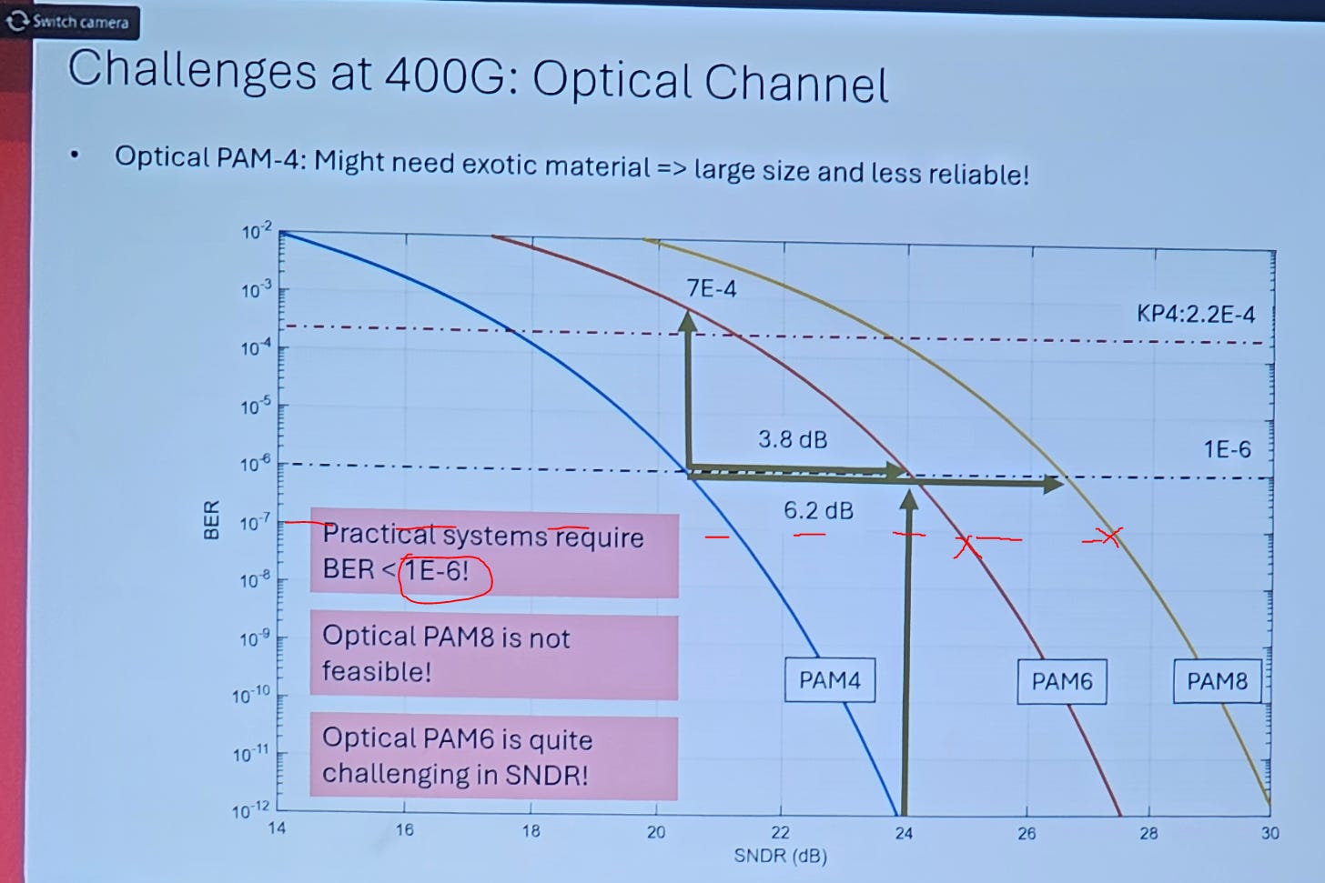
You can hit > 28 dB SNDR with great difficulty electrically but yes Ciena is right you cant hit that optically.
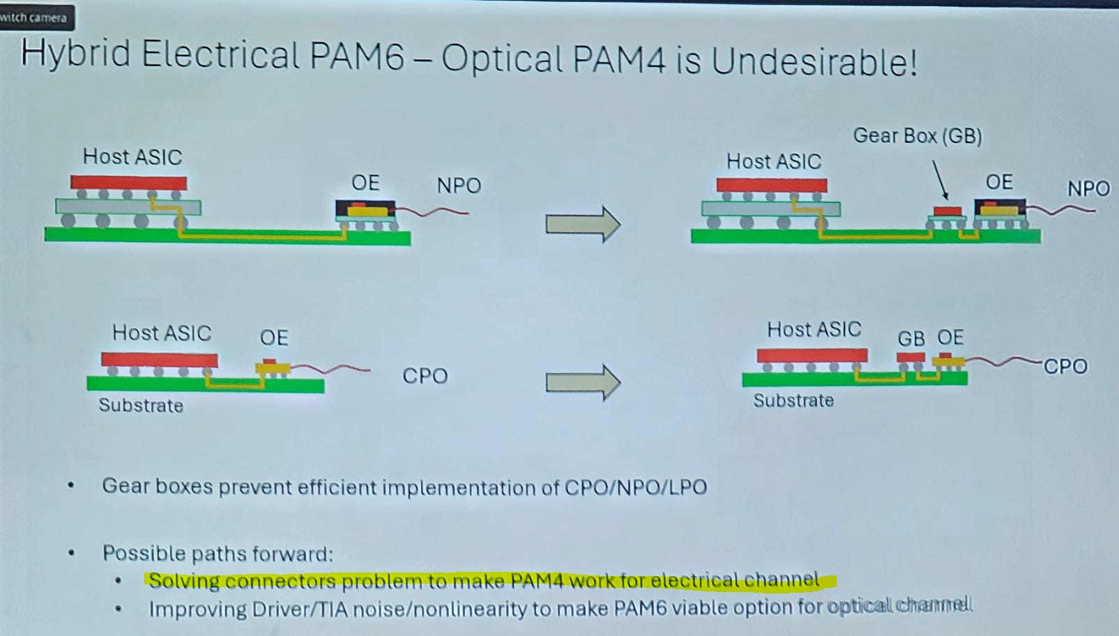
Agree that gearboxing is dogshit solution.
Samtech and TE have good connectors that make PAM4 400G electrically viable. Ciena themselves have a custom connector and package that makes this viable…
Did you guys not talk to each other internally…?
(I am just ribbing them… that connector is for long-haul pluggable InP transceiver, not sipho NPO/CPO)
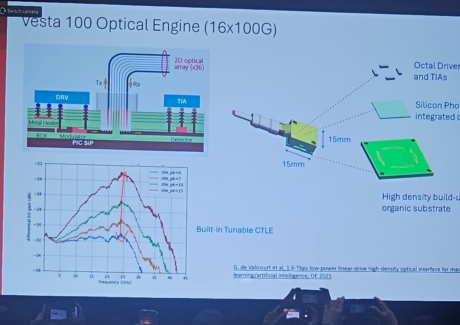
8 dB CTLE gain. Pretty good given how they were probably VERY limited on die area.
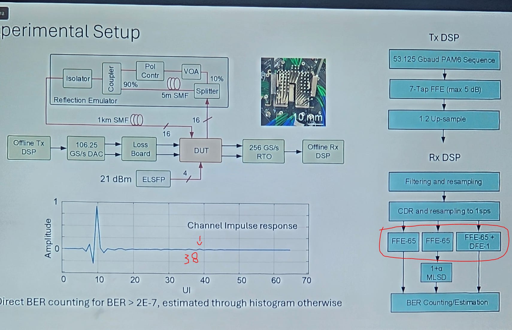
Many people were asking why Ciena has 65 FFE taps (massive power and area burn) given that the channel impulse response only has a far out reflection at tap 38.
Presenter did not do a good job answering this question so let me help him out.
You always over-build FFE taps in the first generation design. Taps can be disabled for a 90% power reduction.
Further iterations you remove taps or switch to a floating/programmable tap system.
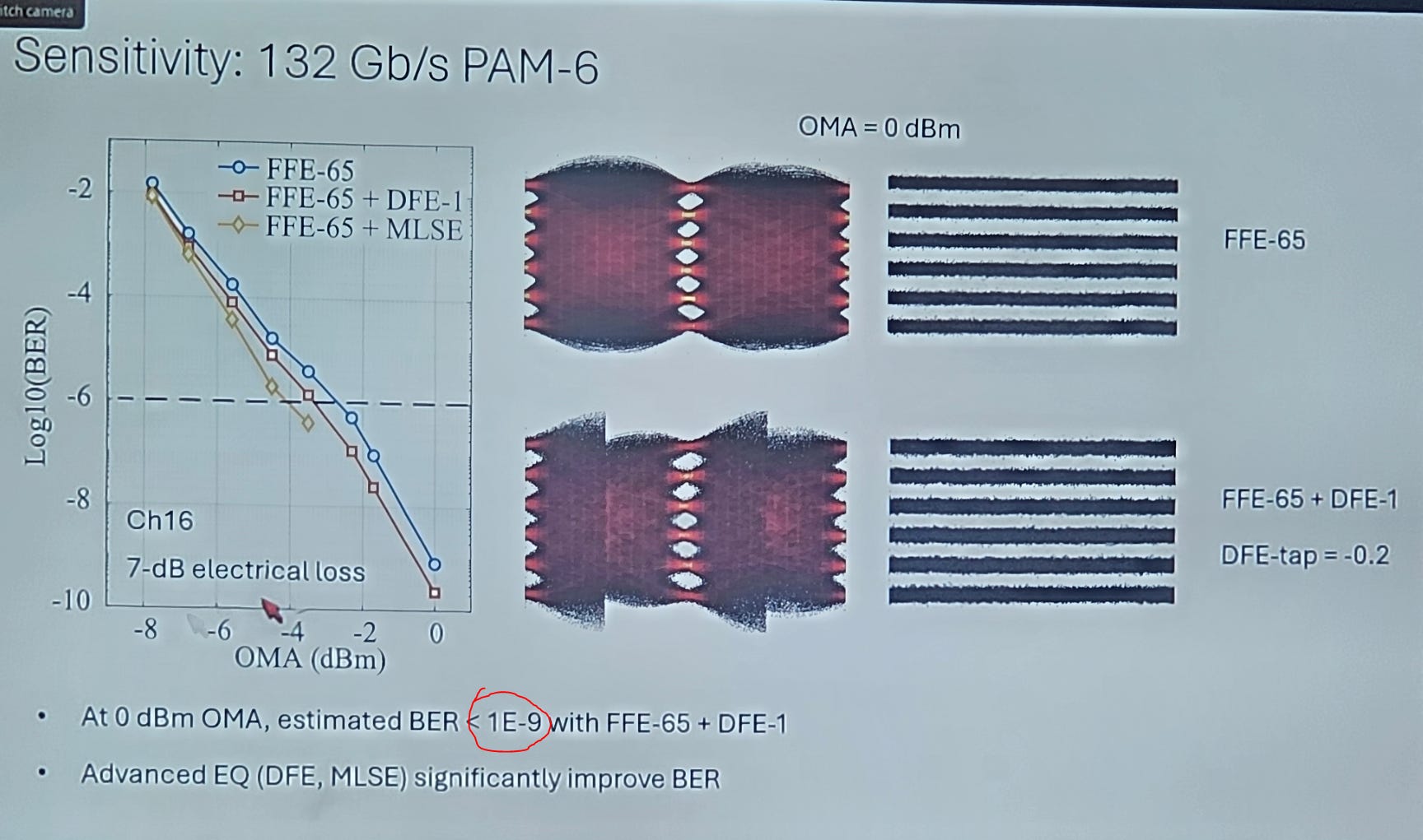
Excellent results.
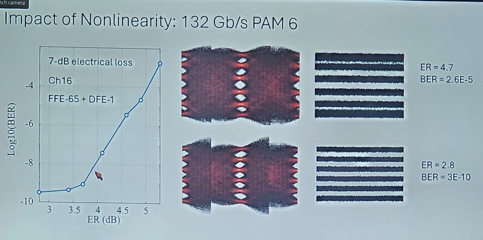
Interesting study on how nonlinearity (low RLM) murders performance. Hear that micro-LED and VCSEL CPO bulls...? LINEARITY IS IMPORTANT.
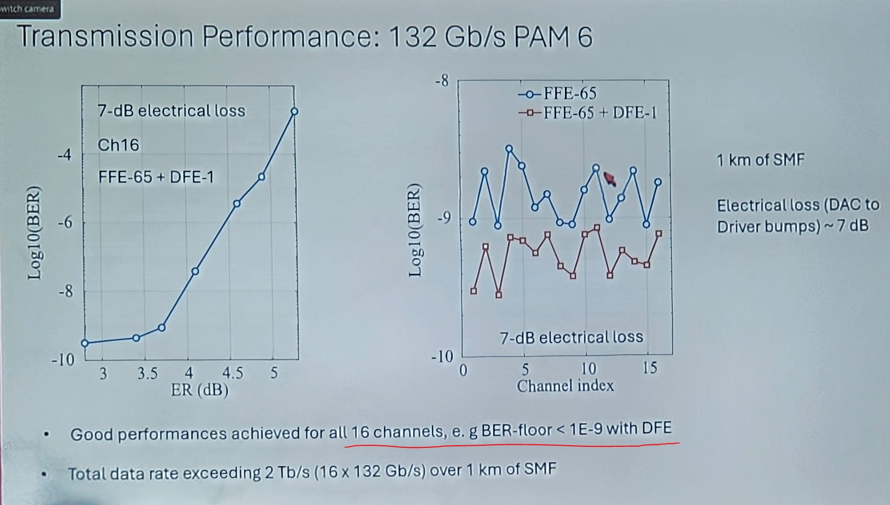
Great performance across all channels. Kudos for showing data with all lanes active, max crosstalk.
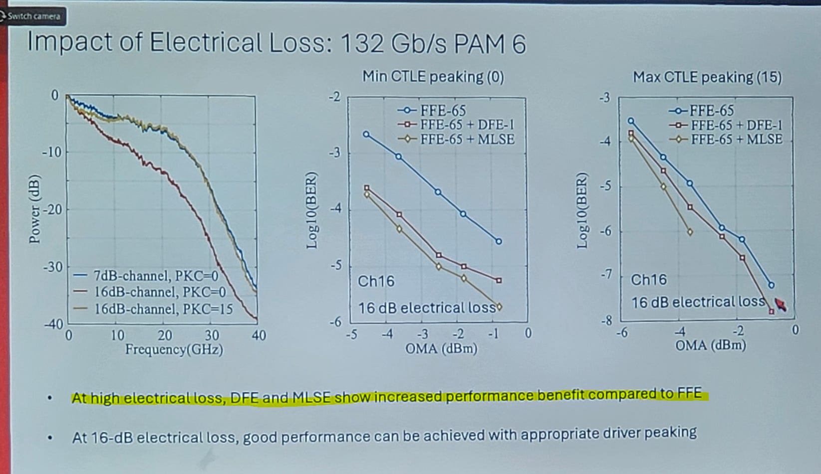
This is correct. Higher electrical loss means higher random errors so DFB or MLSE helps more.
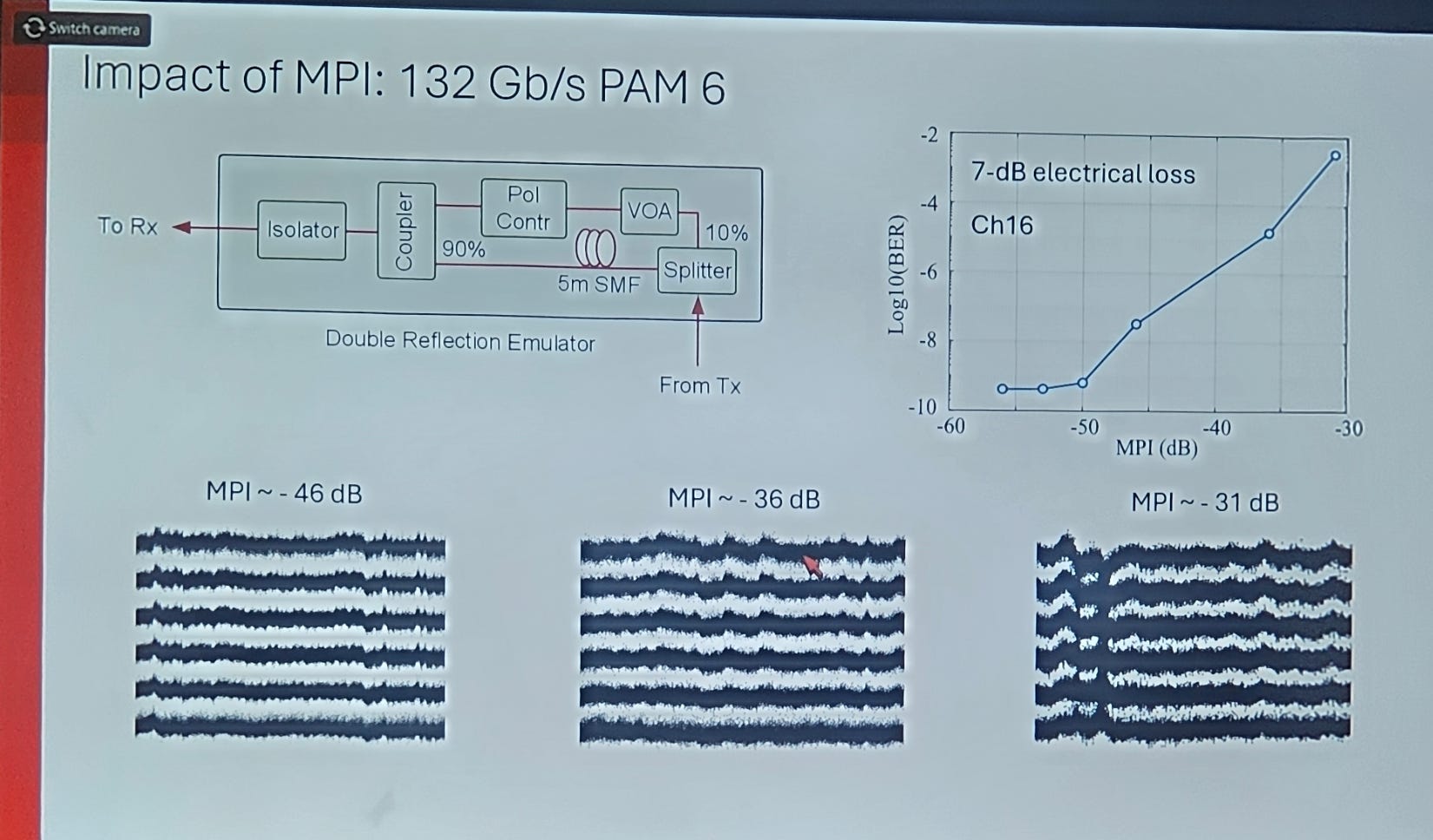
Multi-path interference (reflections or chromatic dispersion) kills the link which is expected.
Overall great stuff. Really enjoyed this presentation.
[1.o] Incredible Santec Tunable Laser
I am familiar with the excellent TSL-570.
They had a demo of the new TSL-580 and holy shit.
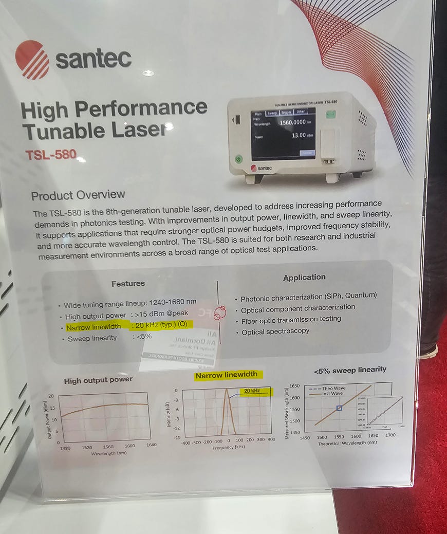
How the fuck did they hit 20 KHz linewidth????
They must be using injection locking in some form.
Incredible product.
[1.p] Arista Super LPO (XPO)
Arista has a new super LPO MSA and it’s beautiful.
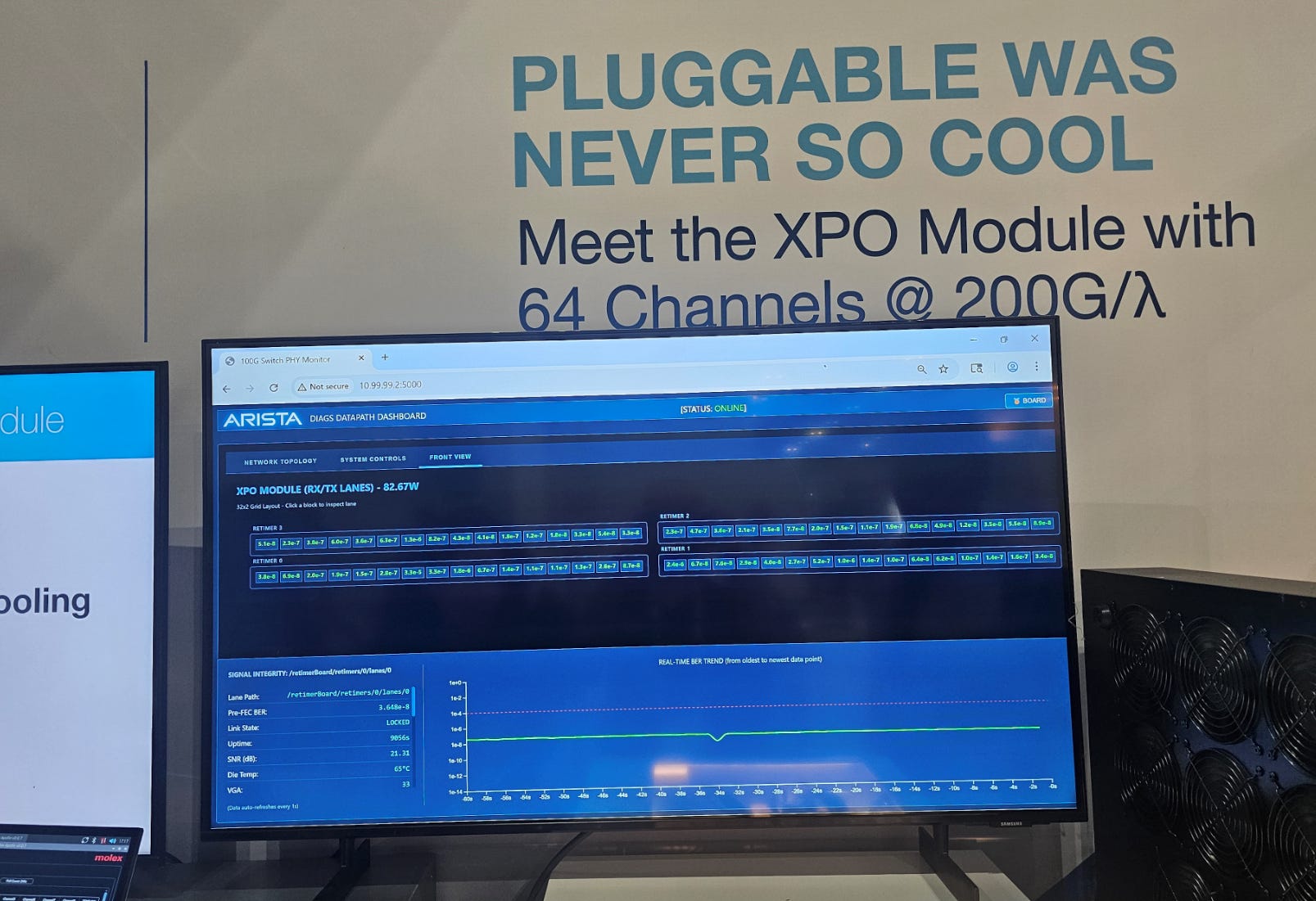
Look at all that tasty content for Semtech! Gona need a lot of analog amplifiers (CTLE, TIA, driver) to make these giant LPO transceivers work.
Fully liquid cooled. This helps performance and power efficiency a lot. Lasers hate heat. Hell, analog amplifiers also perform better at lower temperatures. You generally lose gain at higher die temp.
[2] Cool Shit
There were many papers that were quite interesting to me but rather useless for investment purposes.
Everyone wave to the pod monkeys who just scrolled past this section.

There are 35+ papers and zero planning, ordering, or organization. Don’t have time to make this section readable. Good luck.
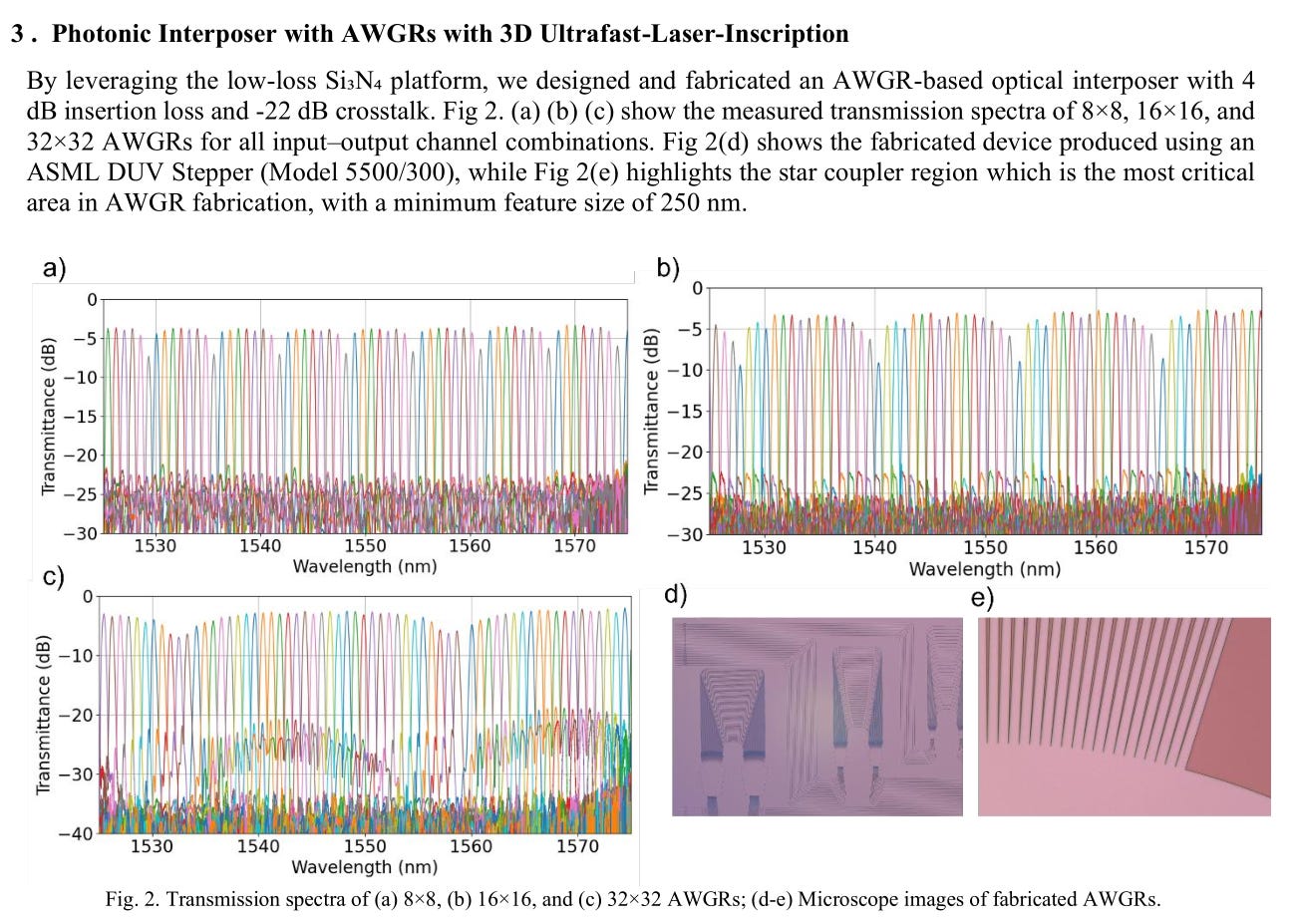
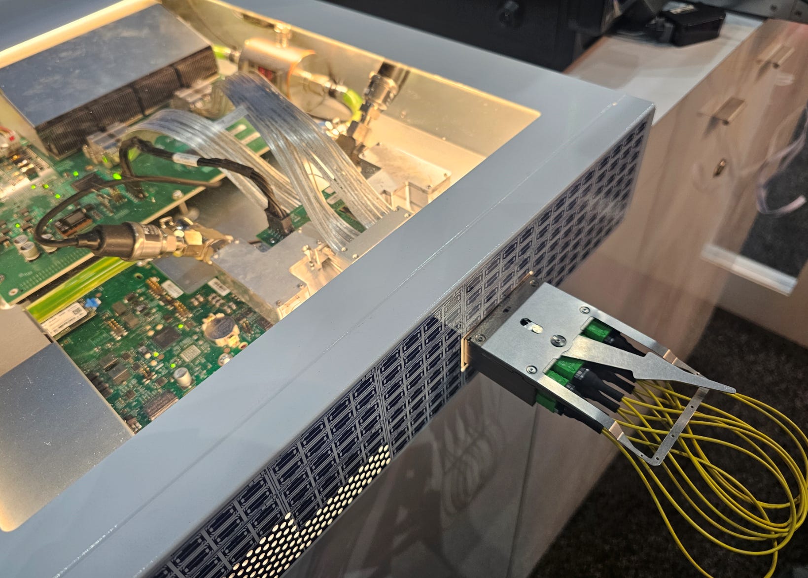
Arrayed waveguides (AWG) are neat photonic structures that have lots of filtering applications. These academics made a rather large router using AWGs.
The insertion loss is bad…
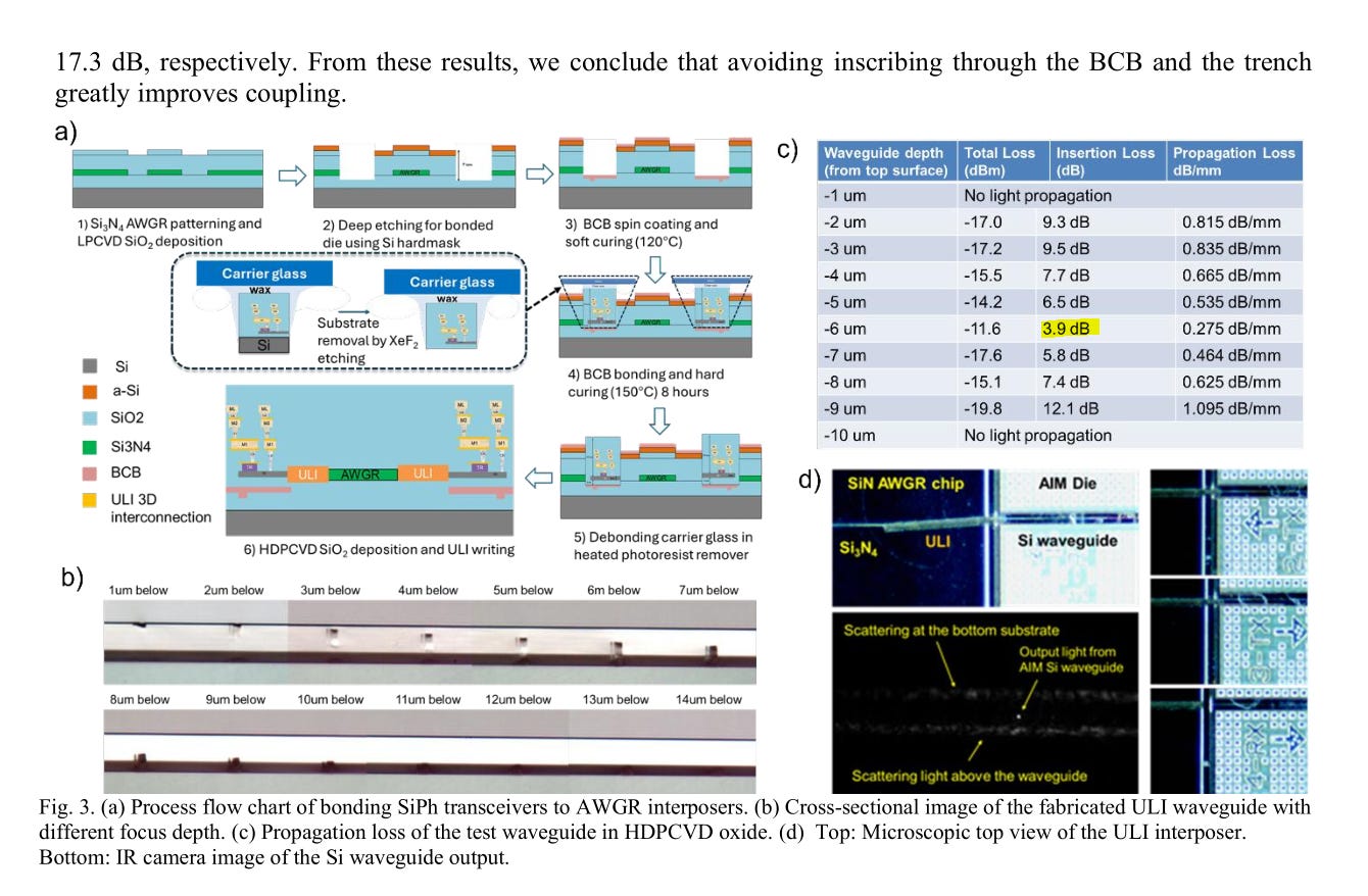
I give Coherent shit for having 2.7+ dB insertion loss on their OCS and the best this AWGR can do is 3.9 dB.
So… useless but very cool research. Great job.
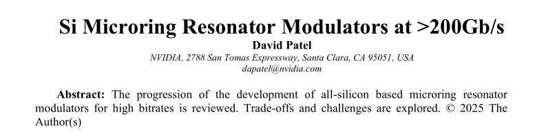
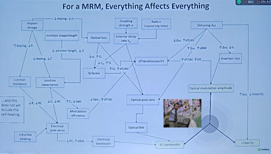
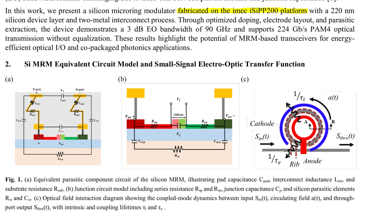
One of the Nvidia people has a great paper and presentation on micro-rings. Some of the diagrams are best I have seen. Saving this for future reference.
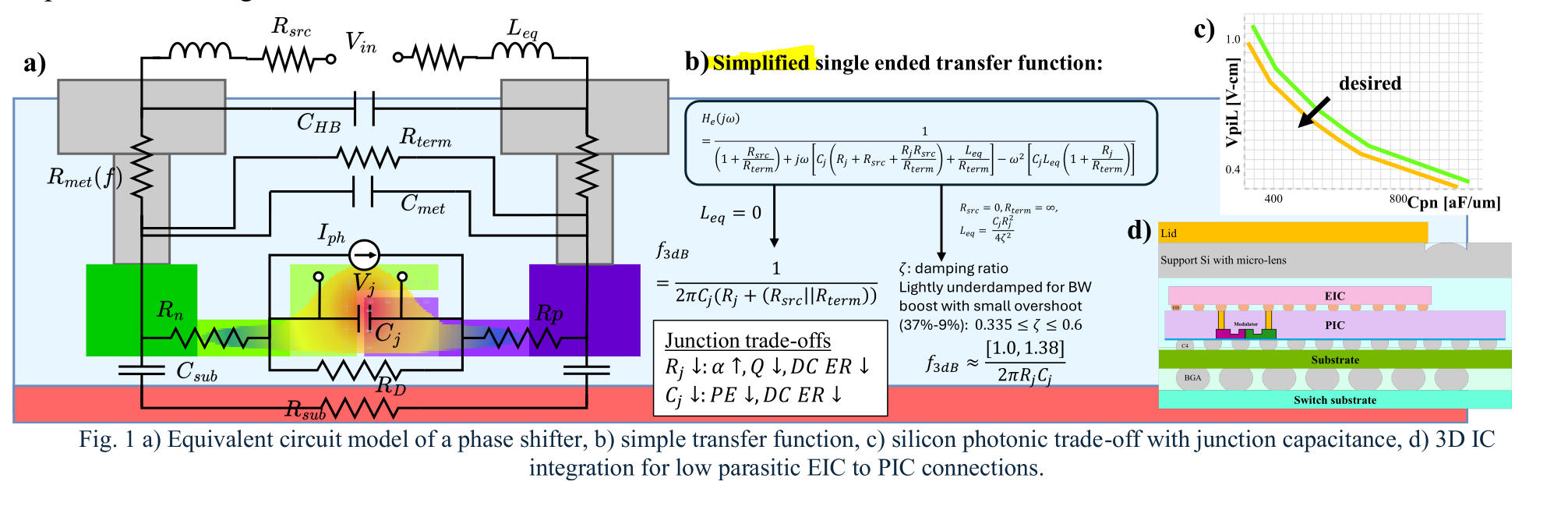

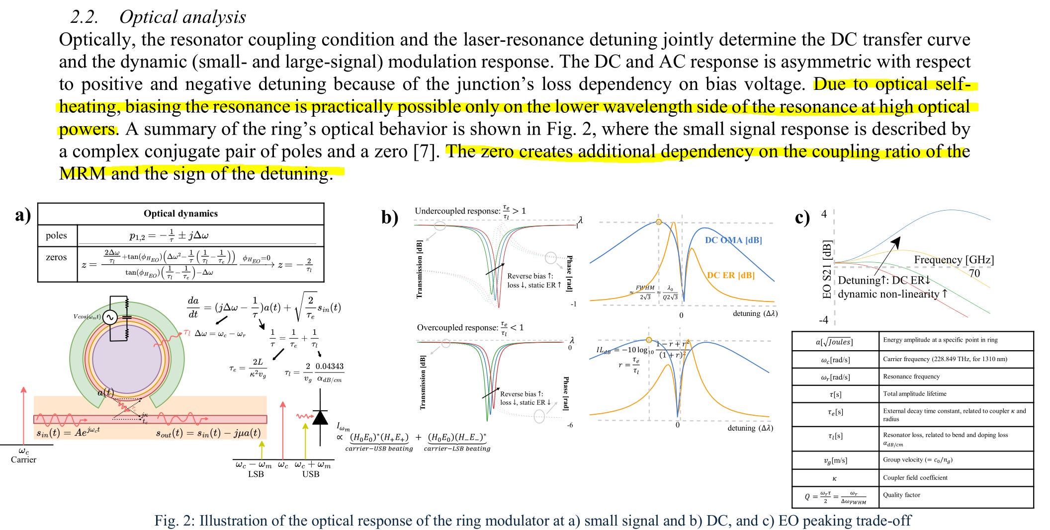
Best diagram of OFC 2026. Never seen pole/zero analysis like this. Super helpful for someone with my DSP background. Need more time to play with these transfer functions in MATLAB.
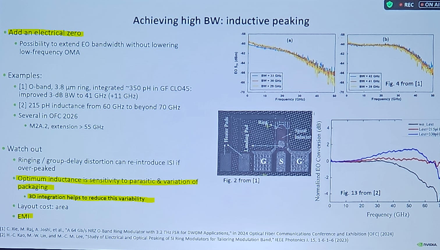
Inductive peaking is absolutely crucial. Process variation kills you. If you avoid that, poor shielding kills you.
Inductors act as antennas. Pick up shit you dont want. MANY problems happen because something dumps noise into an important inductor, say the inductor responsible for CTLE peaking.
This is true. Self-heating effect on detuning is particularly painful.
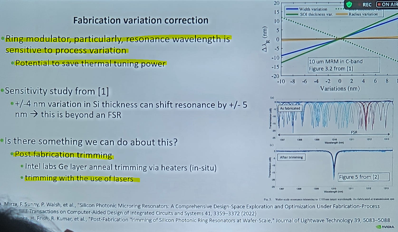
You want the laser wavelengths and ring resonance to be as close as possible to save thermal tuning/shift power.
Fab variation usually makes this impossible but there are clever ways of adjusting ring resonance after fabrication.
These involve FiconTec machines outfitted with a special add-on from a private Canadian company called Femtum.
Basically blast the SiPho chip with a laser to permanently warp the Si/SiN waveguide, shifting refractive index.
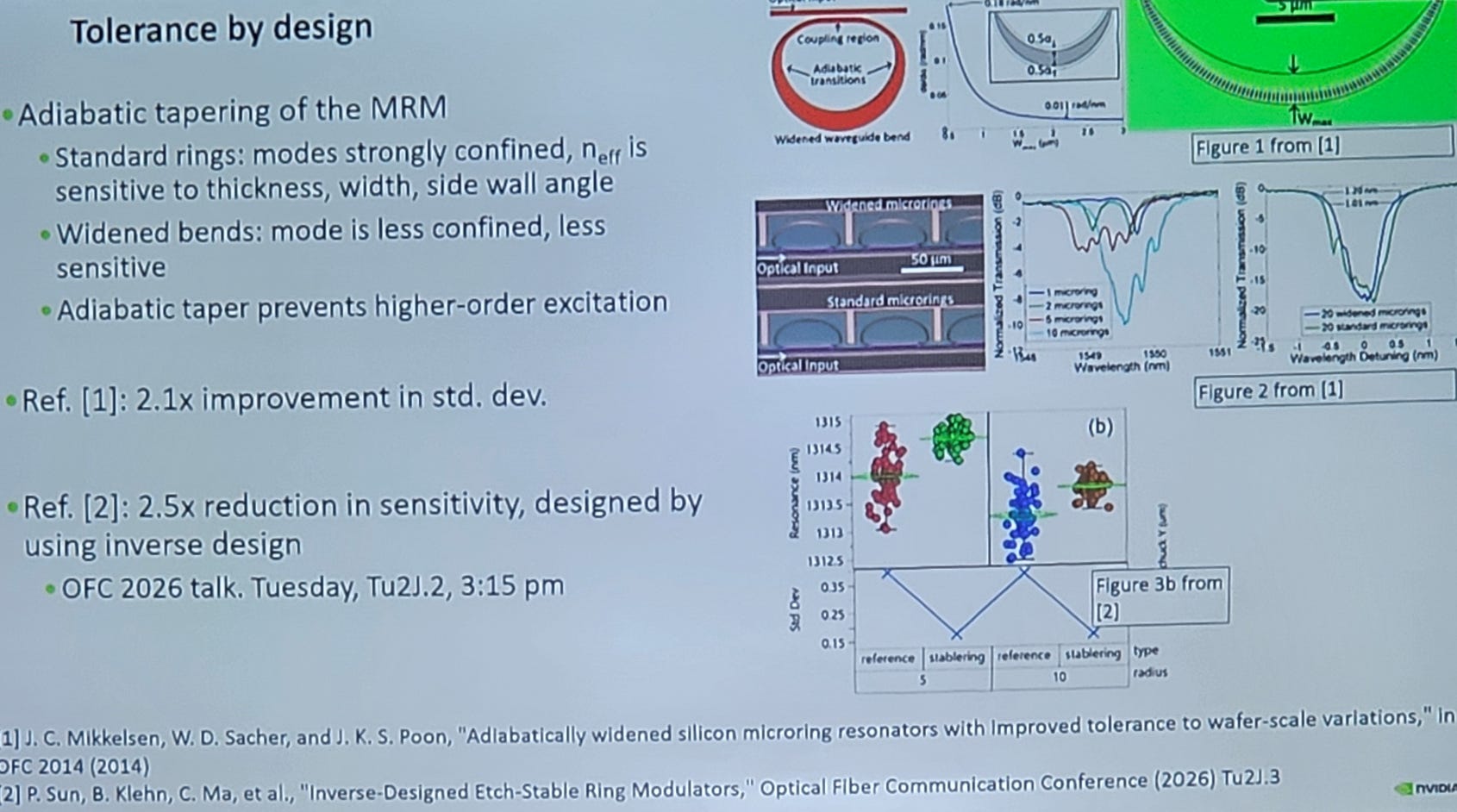
I don’t think anyone is using these wider/strange dimension rings. Laser trimming is straight up better.
Parasitic capacitance kills bandwidth and linearity.
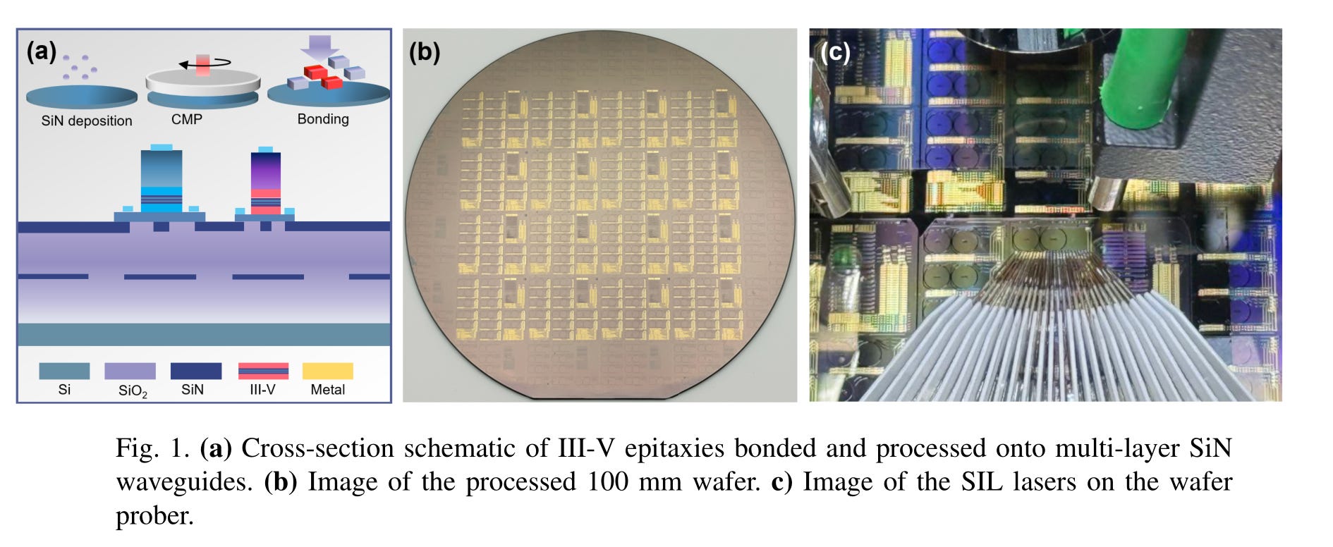
Injection-locking is a strategy that greatly reduces noise of lasers. Basically, shove some of the laser output back in a controlled manner.
This is very difficult to do in an economically viable manner.
(notice they are using 100 mm SiN wafers)
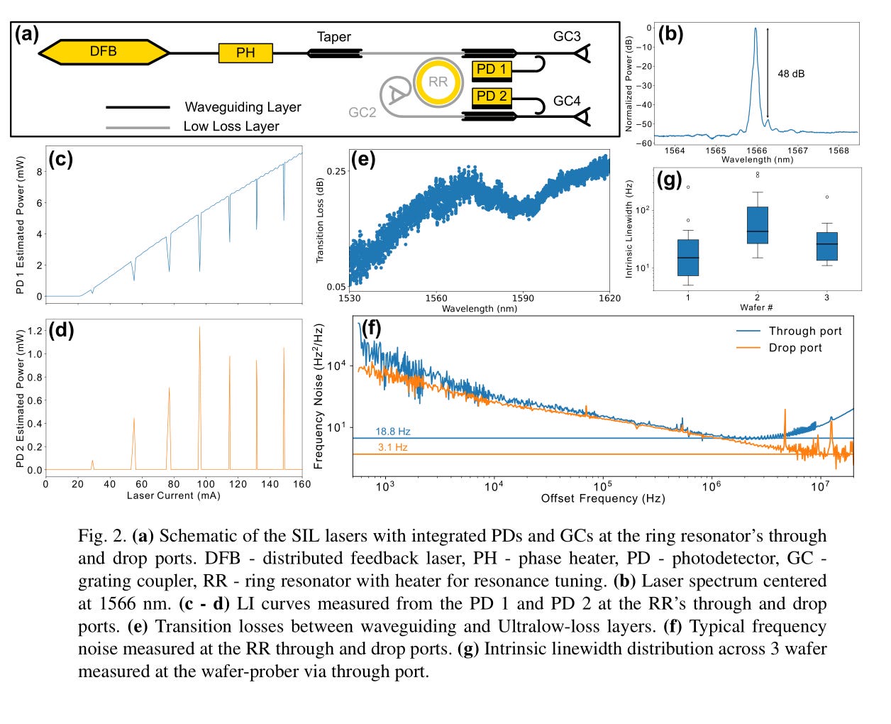
I am annoyed they only have intrinsic linewidth. Effective linewidth is what actually matters. Whatever moving on.
Samsung Foundry has sipho now. This is news to me. Let’s see what you got!
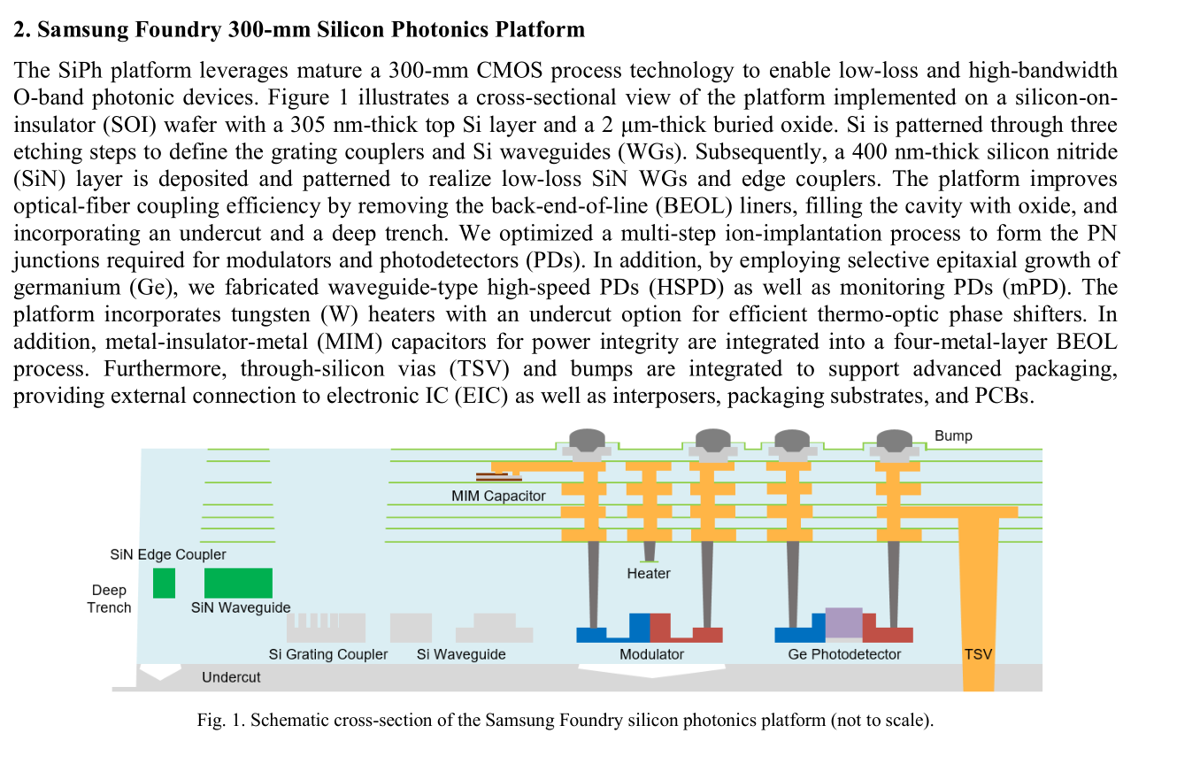
SiN and MIM cap support. Good.
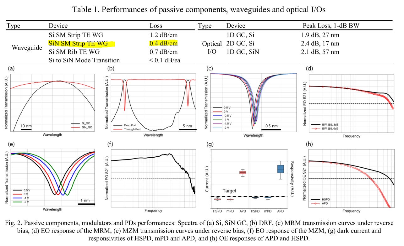
SiN waveguide loss a little higher than I would like to see but still pretty good.
None of the chats have properly labeled y-axis. :(
Honestly, Samsung Foundry sipho is probably better than GloFo. LOL
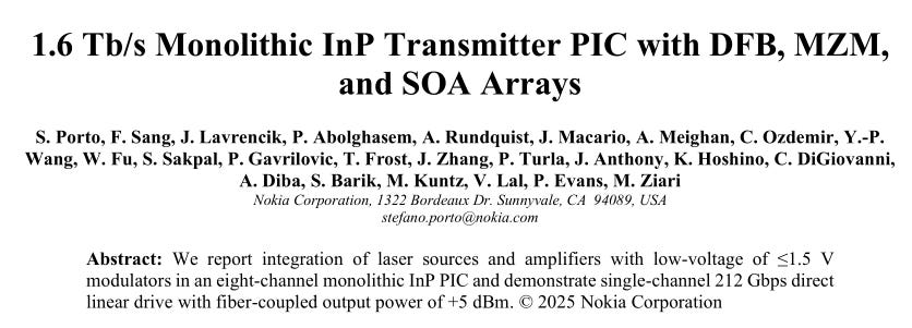
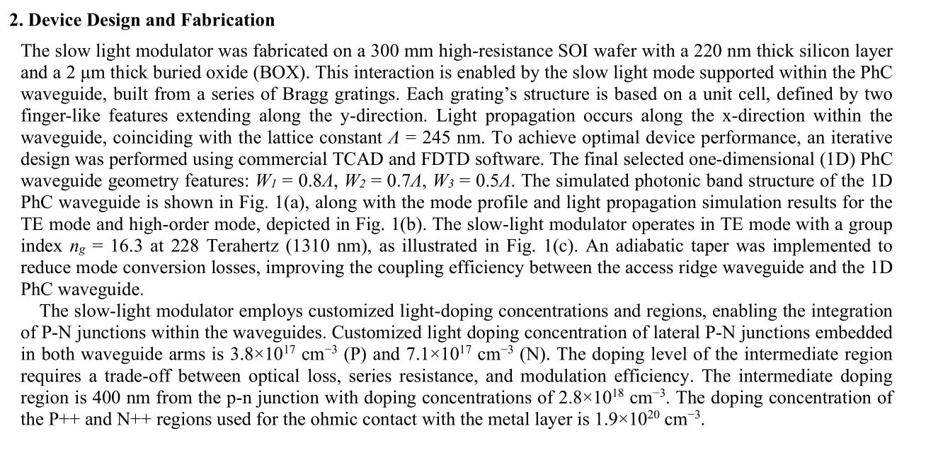
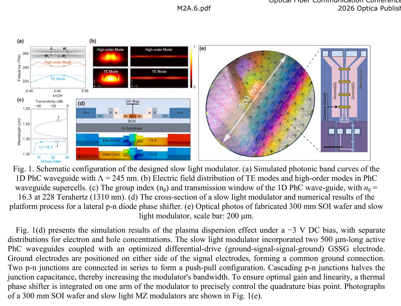
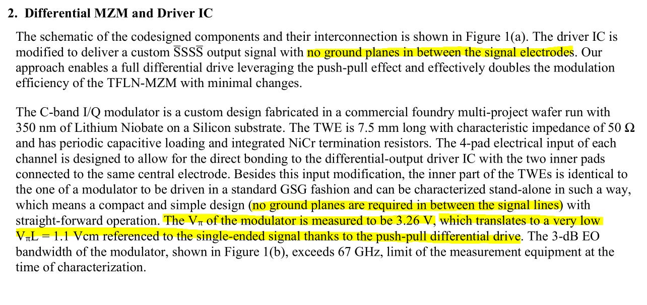
First Nokia paper. Low voltage is a big deal. Most photonic modulators really need > 2 V swing to work properly.
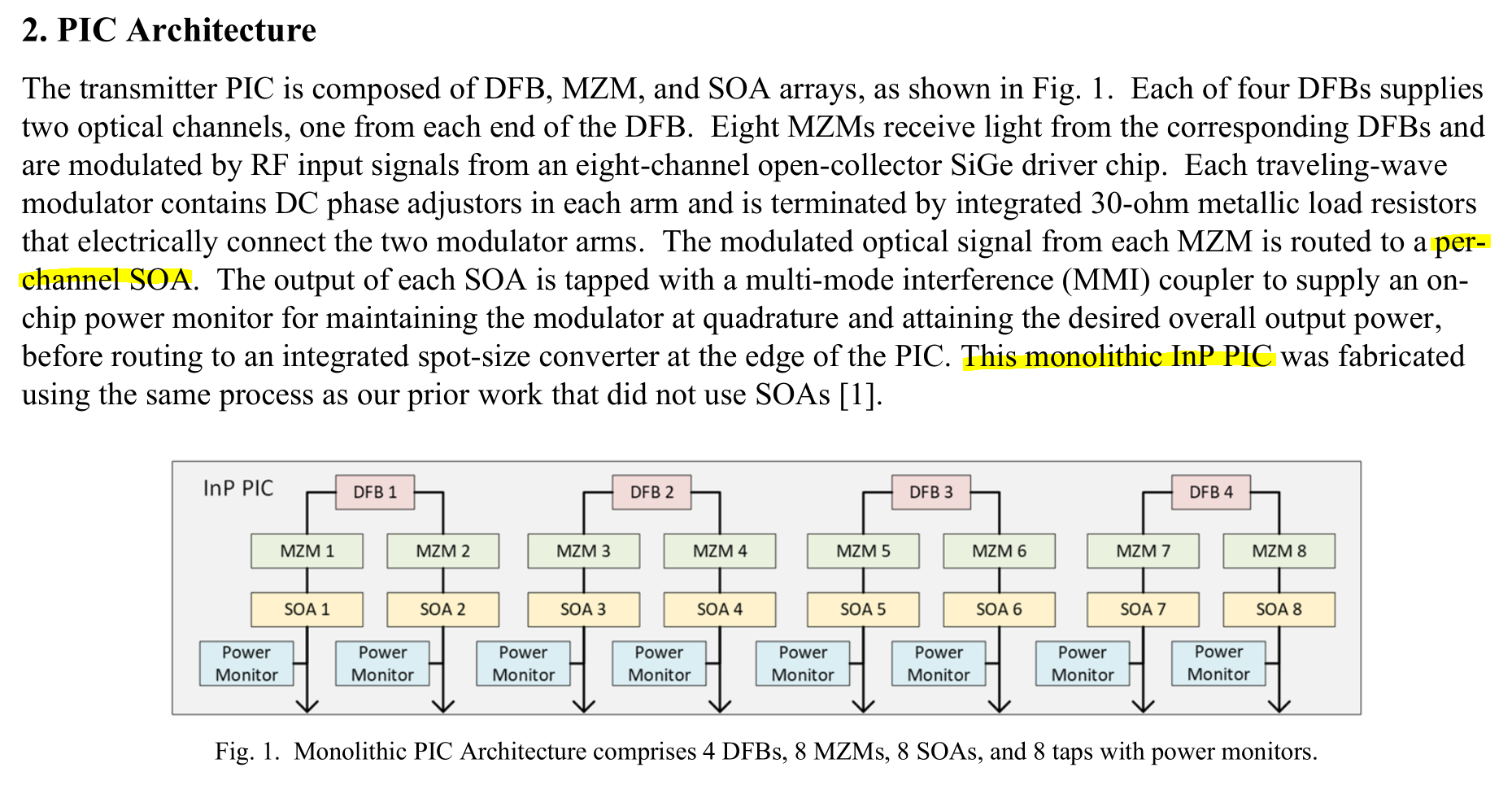
The drawback of monolithic InP is high cost.
But at least they shove a ton of SOA into this PIC lol. Helps a lot with perofmrance.
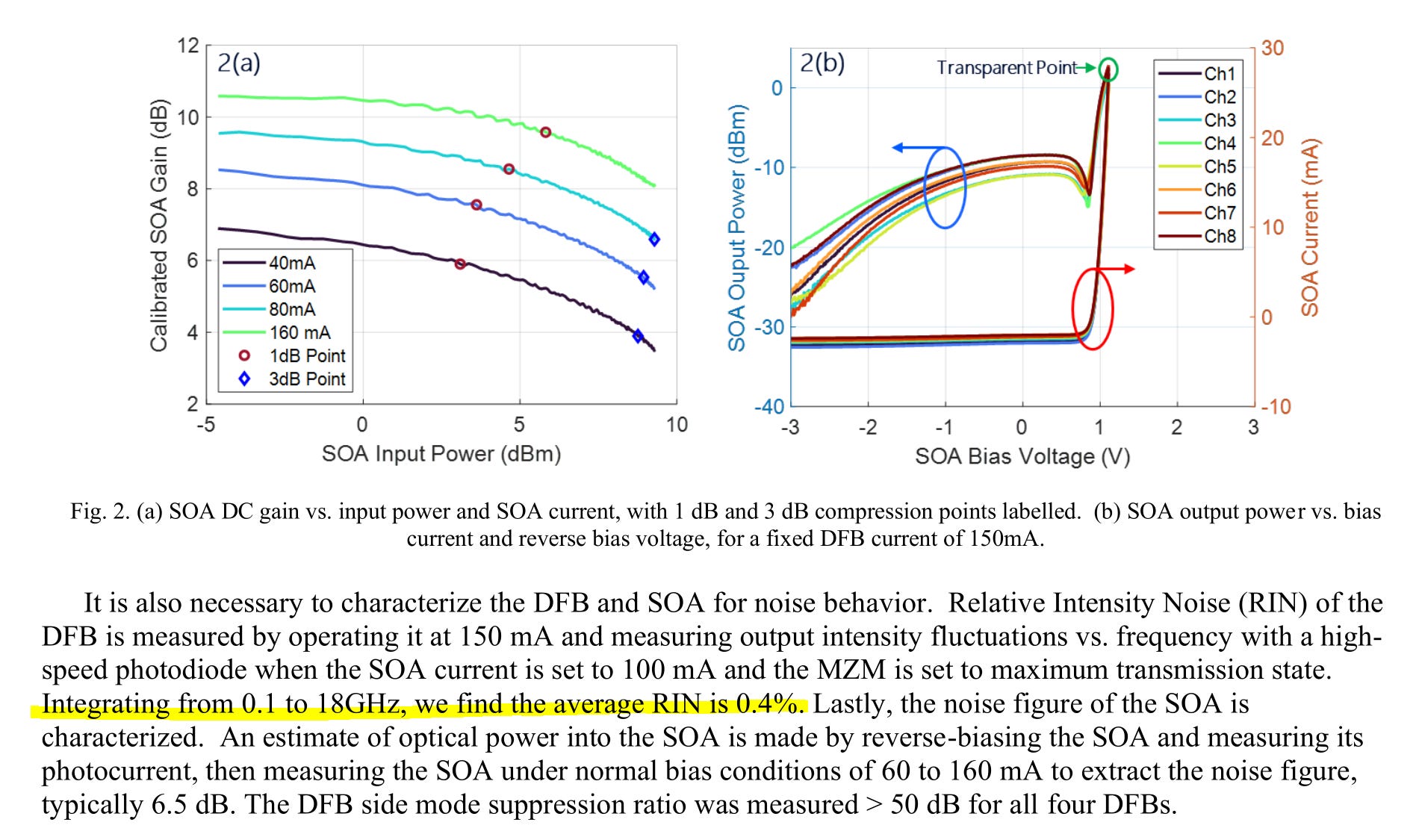
Guys you are supposed to report RIN in dBc/Hz
Let me quickly do that math for you.
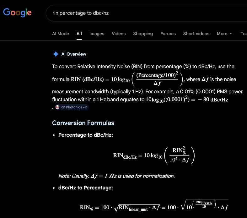
-150.5 dBc/Hz
Wow pretty good!
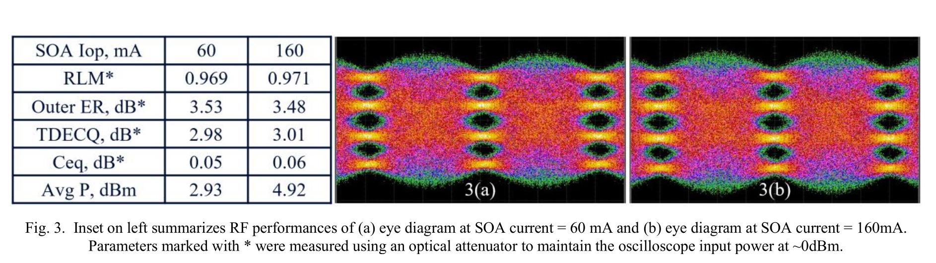
Very impressive that boosting SOA current has effectively zero impact on TDECQ. Excellent!
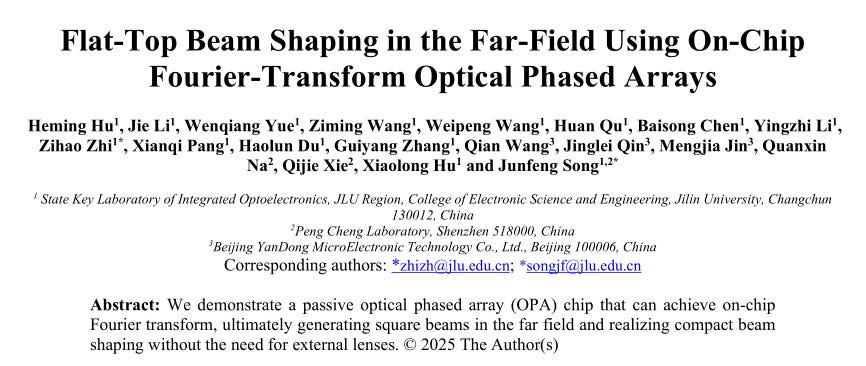
Calculating Fourier transform using phased arrays?
This is completely useless and FUCKING AWESOME.
I love phased arrays.
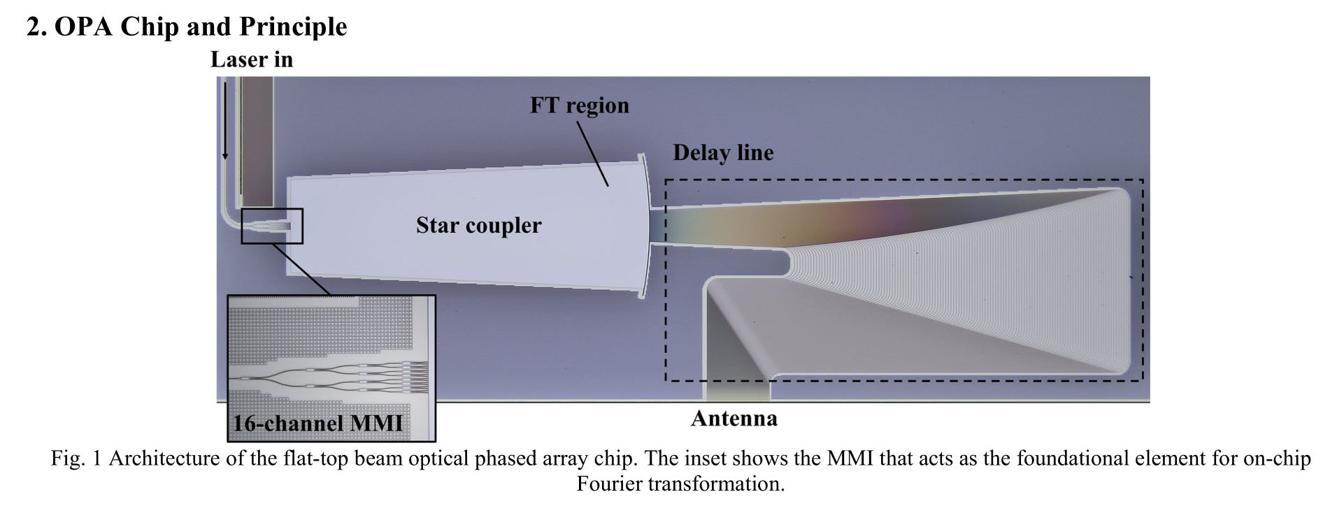
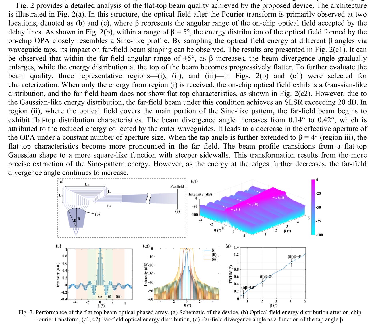
The sync functions look pretty clean but this is a simulation of course.
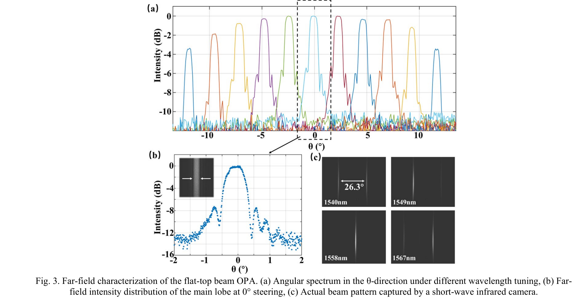
Honestly not bad. Don’t like the asymmetry but better than I expected.
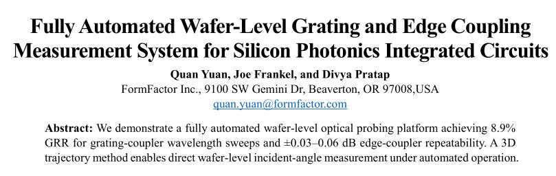
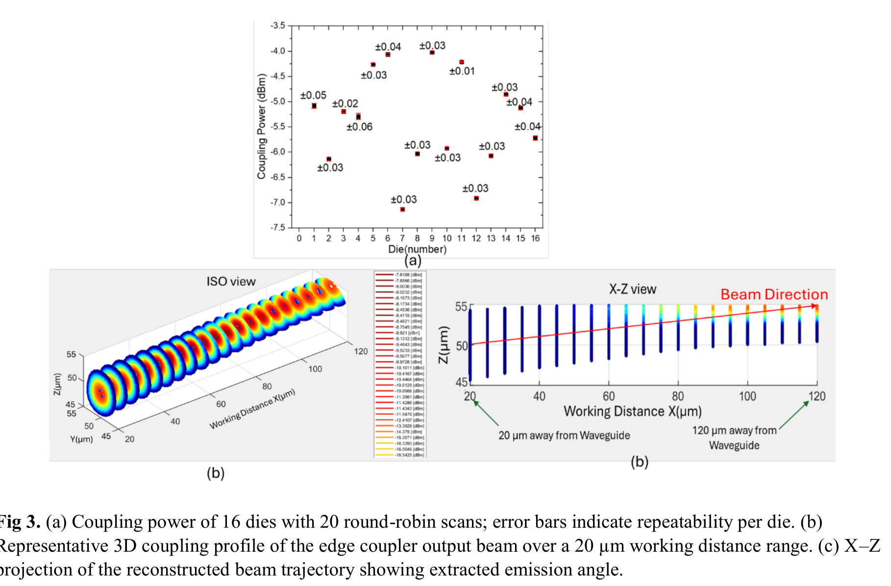
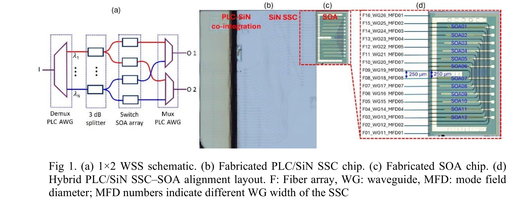
Excellent repeatability results for both grading and edge coupler characterization.
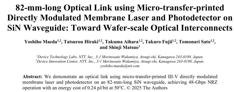
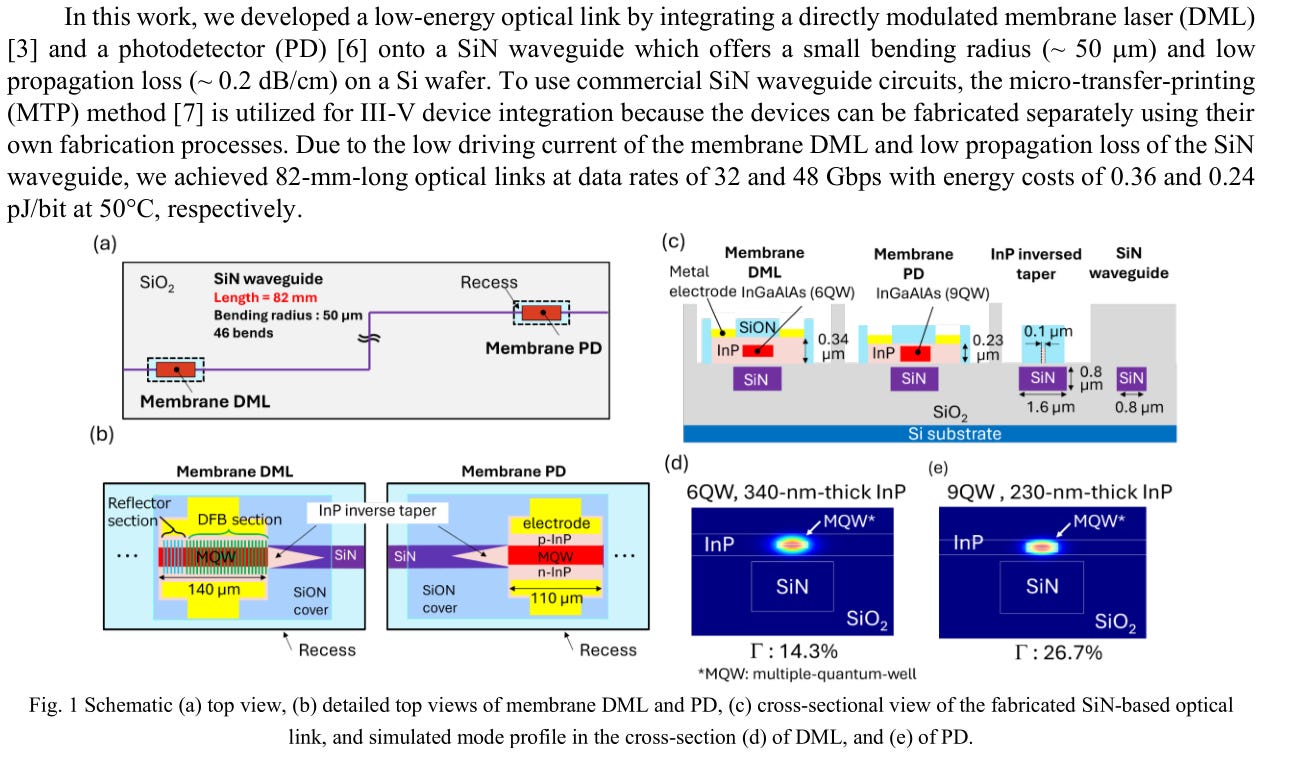
Never seen something like this before. Hybrid integration of directly modulated (not VCSEL) laser. Very unique.
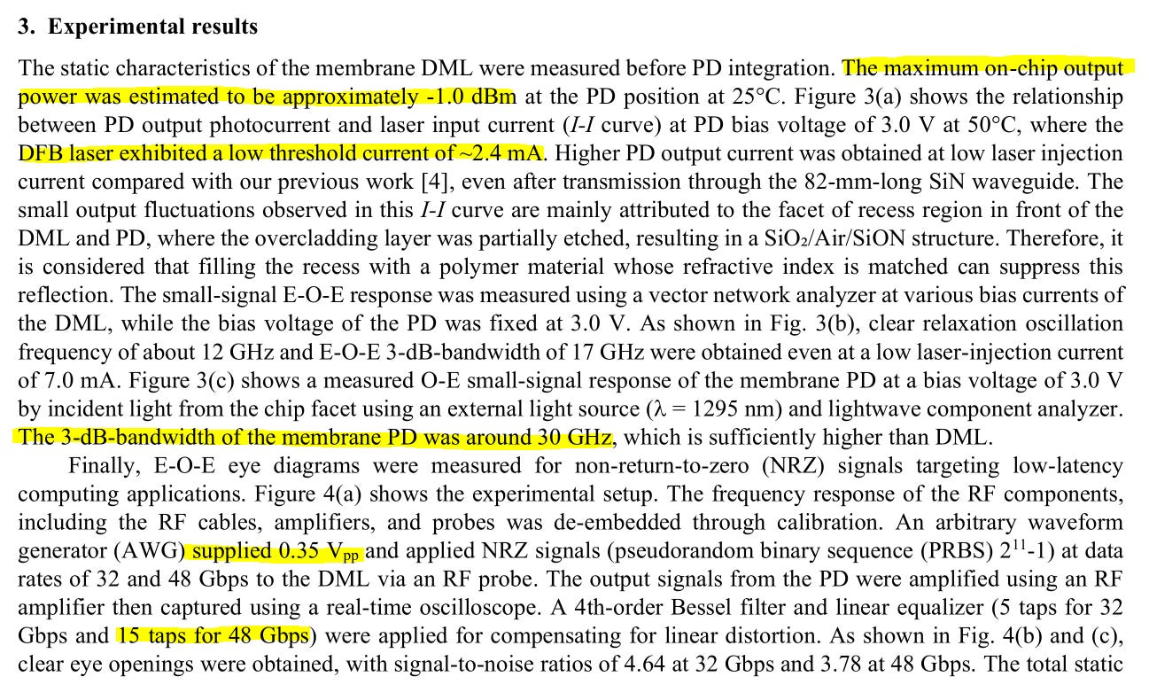
Yea… 15 FFE taps is rather heavy for this style of link. Power is super low though.
(does not matter because the FFE taps burn crazy power lol)
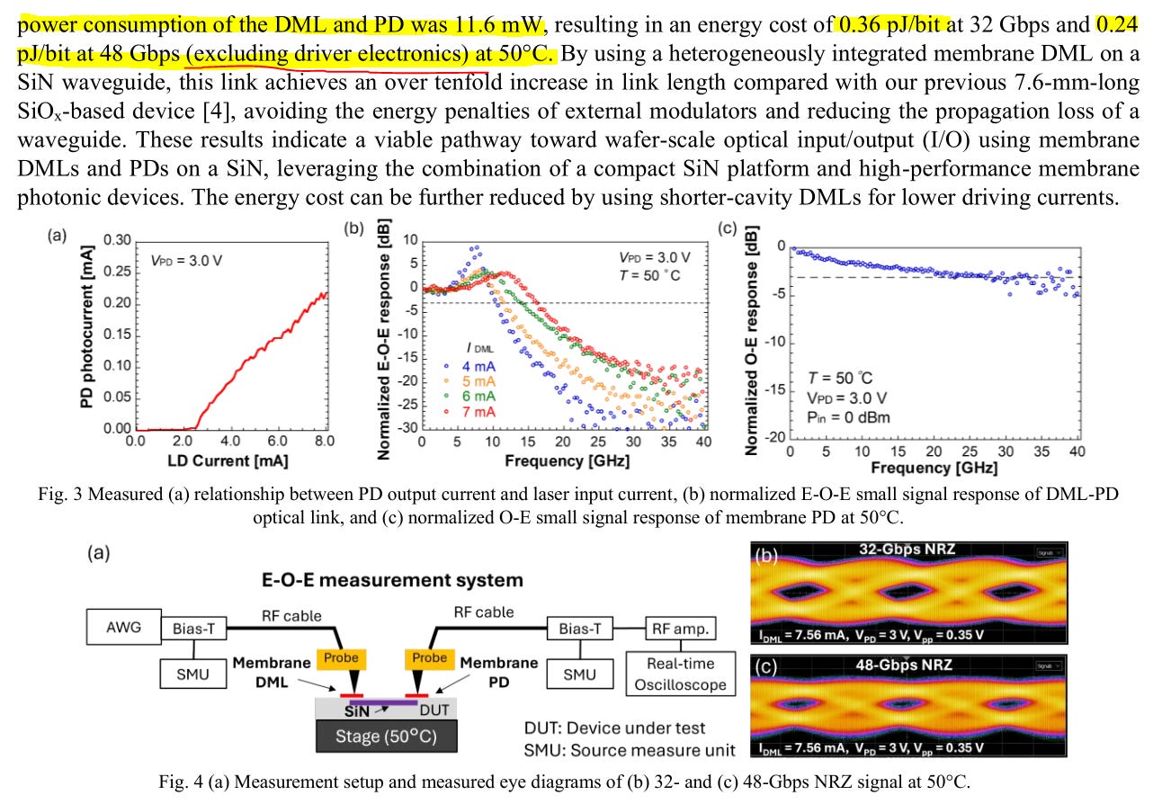
Guys your driver electronics probably contribute 2-4 pj/bit lmao.
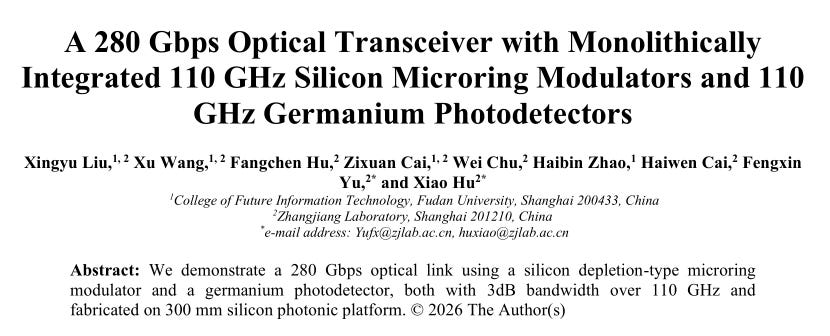
Impressive numbers. Let’s see the details.
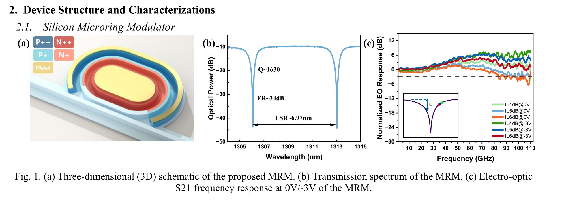
Very impressive ER and bandwidth.
PD has some undesirable response at 80 GHz but overall pretty good.
FFE can fix this.
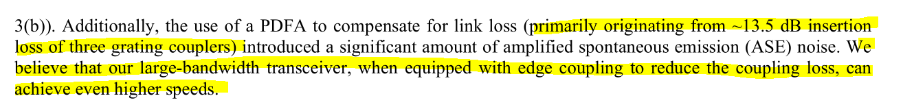
I won’t ding them for using PDFA. Grating couplers great for R&D. In reality this tech would be used with edge coupling in high-performance transceivers.
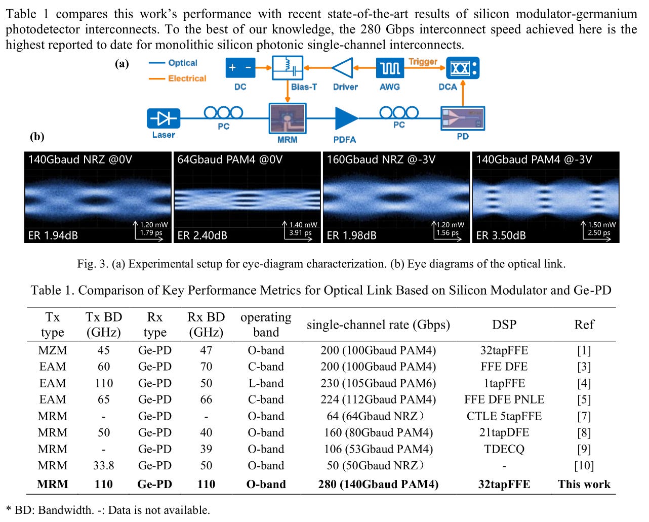
Impressive results. Could be better if they add a DFE tap.
RLM calibration is what caught my eye.
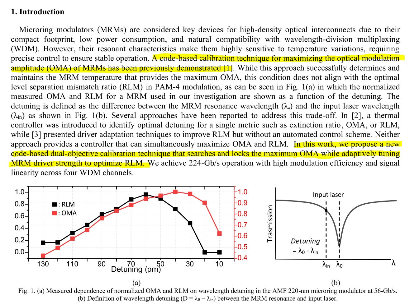
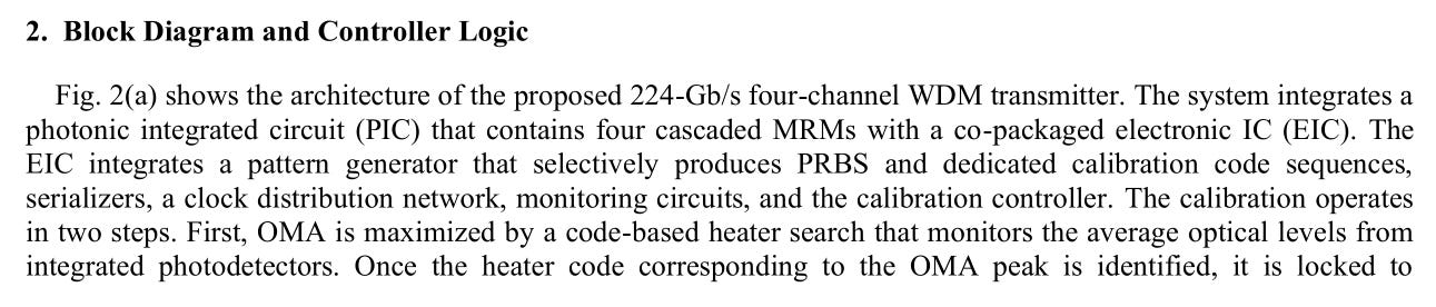
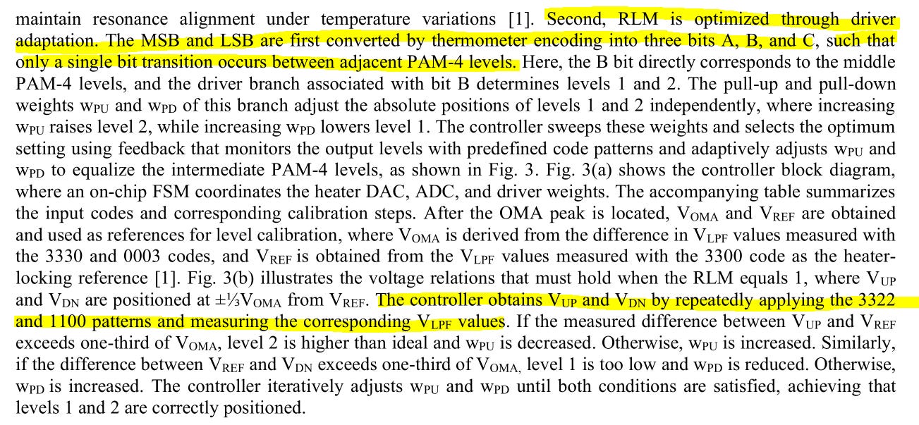
This strategy almost reminds me of channel sounding. Very clever.
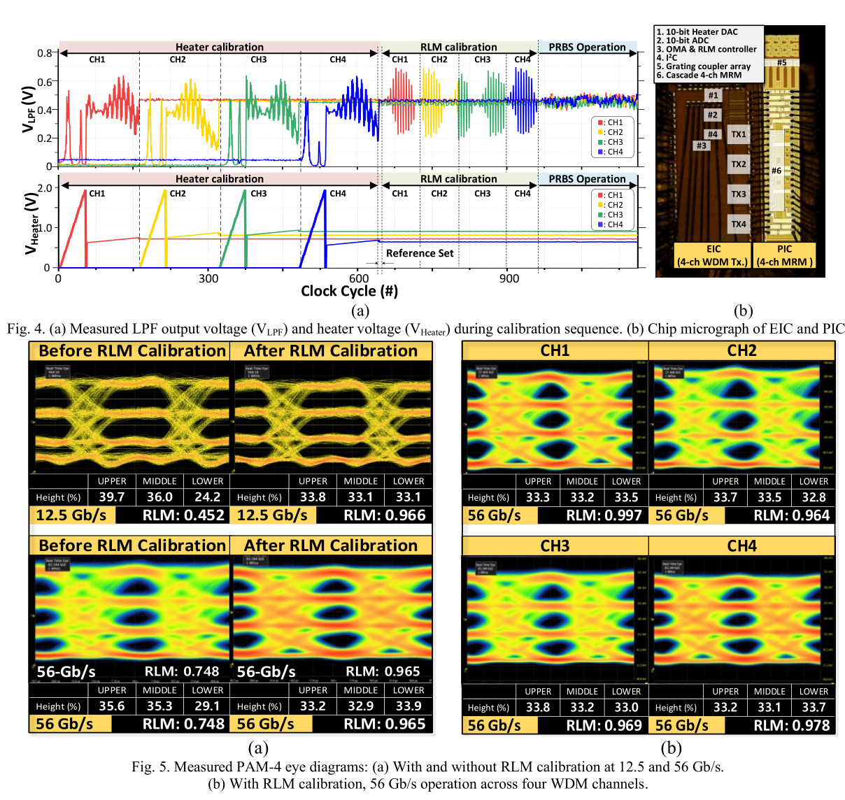
Most wireless systems use Zaddoph-Chu sequences and autocorrelation. These Samsung guys use much simpler codes.
Absolutely massive improvement in RLM.
Very impressed by this.
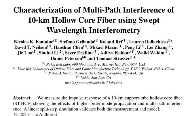
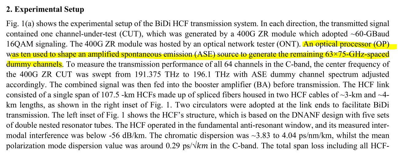
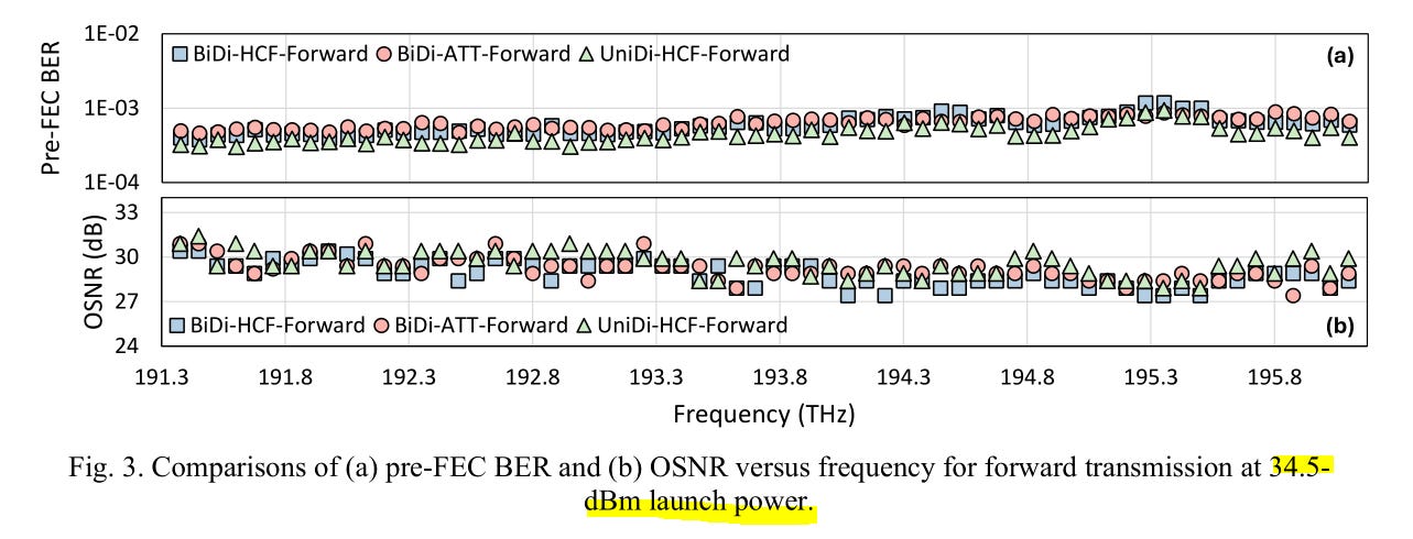
Speaking of channel sounding…
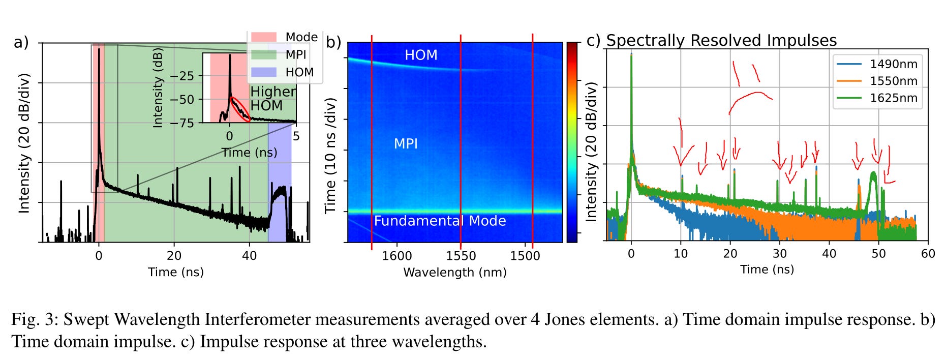
Surprising how nasty hollow-core fiber impulse response is. Good thing Nokia people spent the time to properly characterize.
This is IMEC, not TSMC, process node.
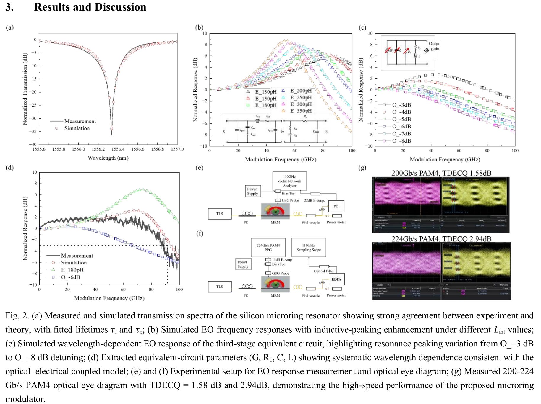
Good matching between simulation and measurement. Marginal pass on TDECQ for 224G.
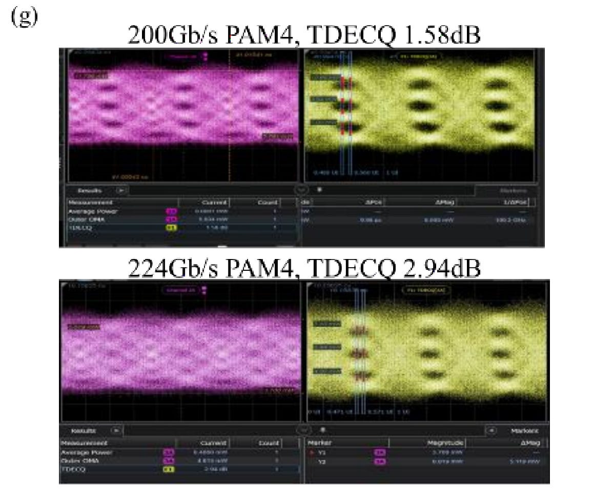
Weird how much worse the 224G result is compared to the 200G result.
Taking another look…
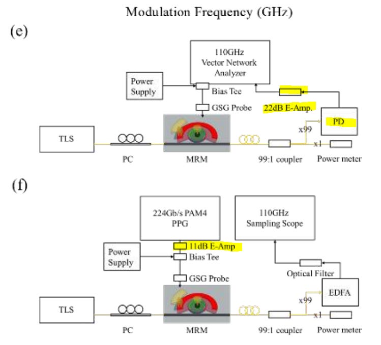
The test setup is completely different. All that nasty noise in the 224G eye is probably coming from the discrete 11 dB electronic amplifier.
They did not disclose the model numbers for the 11dB or 22 dB electronic amplifiers. My guess is that 11 dB amp is either lower quality or was over-saturated.
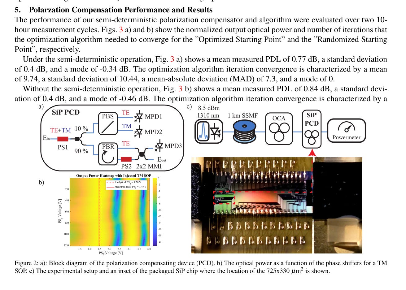
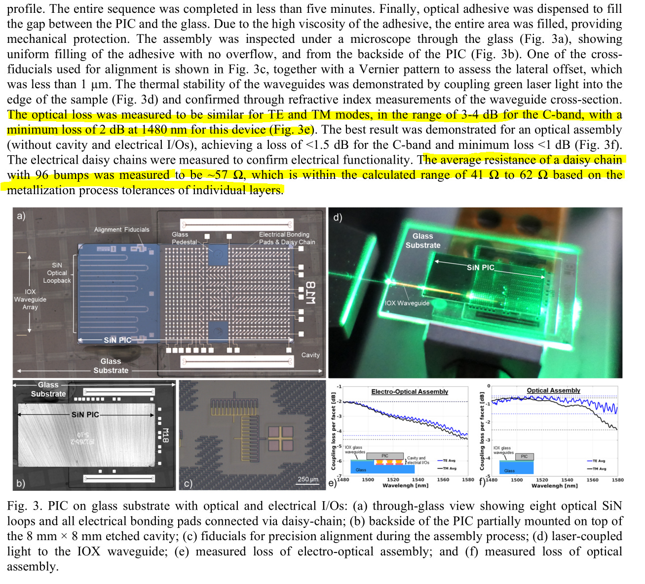
Avoiding PM fiber for ELS is great. Suffering 1.9 dB of loss to achieve this is unacceptable.
Very cool but quite useless. Solution looking for a problem.
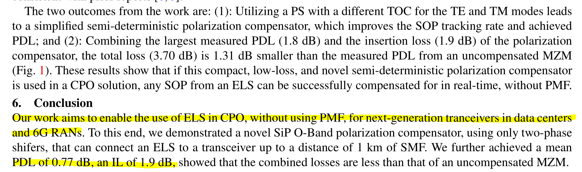
The loss is still way too high. Just co-locate the damn ELS and have a short run of PMF.

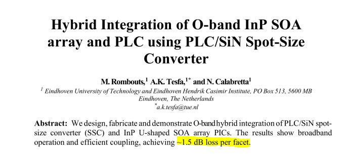
1.5 dB is not great TBH. You can get ~1 dB loss with a well-designed 2-lense system on an optical bench.
But obviously cost of active alignments very high.
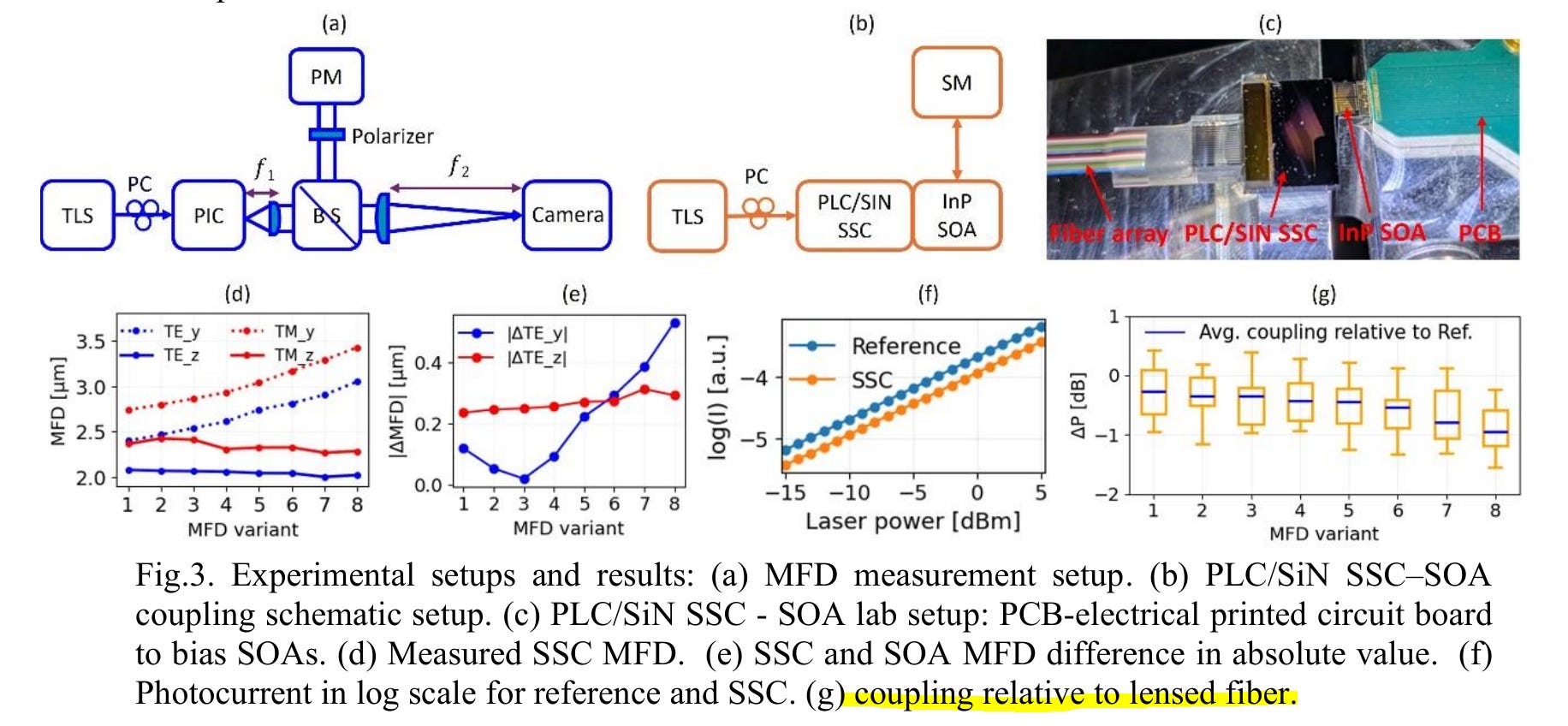
So your specialty, unproven/exotic process is meaningfully (more than 0.5 dB) worse than lensed fiber.
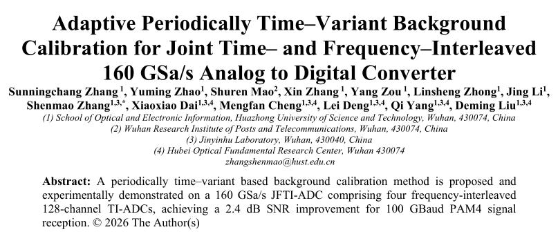
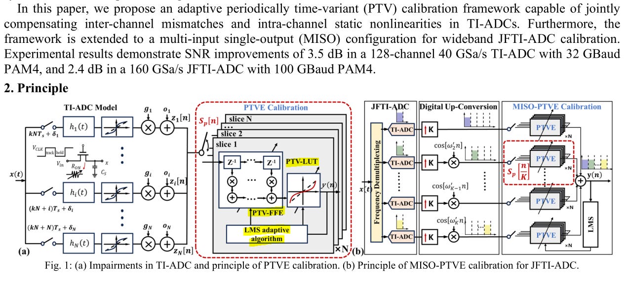
A FFE, LMS block, and even a LUT for calibrating ADC interleaves.
Looks expensive in terms of power and area.
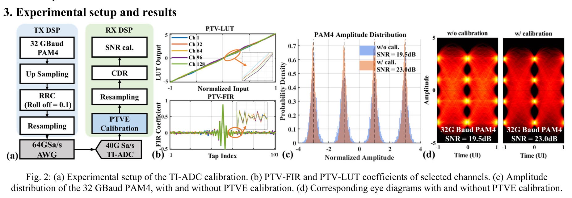
Decent performance gains, but at what cost?
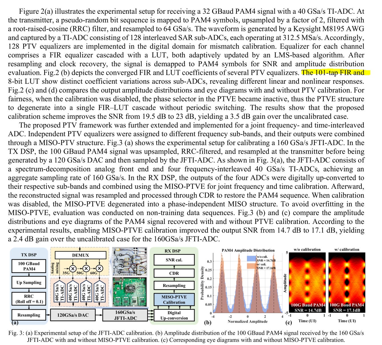
110-tap FIR per ADC interleave.

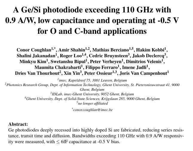
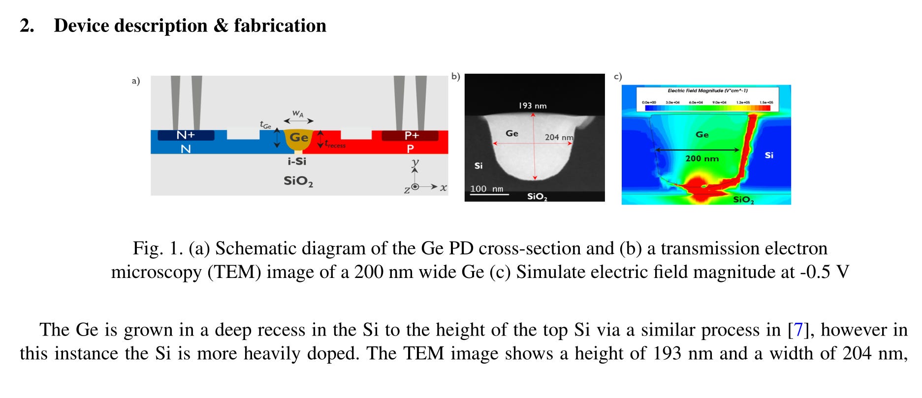
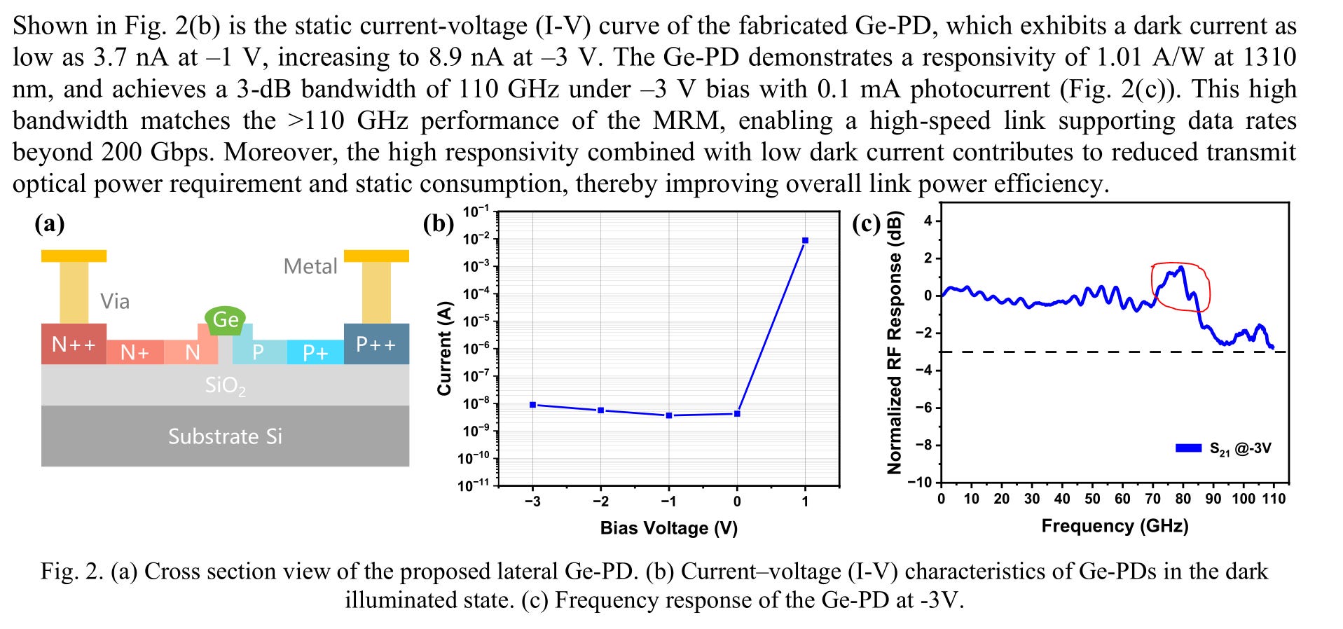
Ge PDs are usually built with thin film epi. This paper shows an unusual deep-recess process.
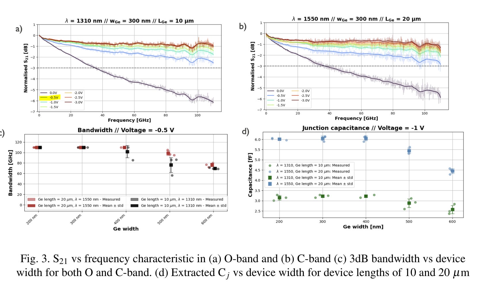
Exceptional bandwidth at very low voltage.
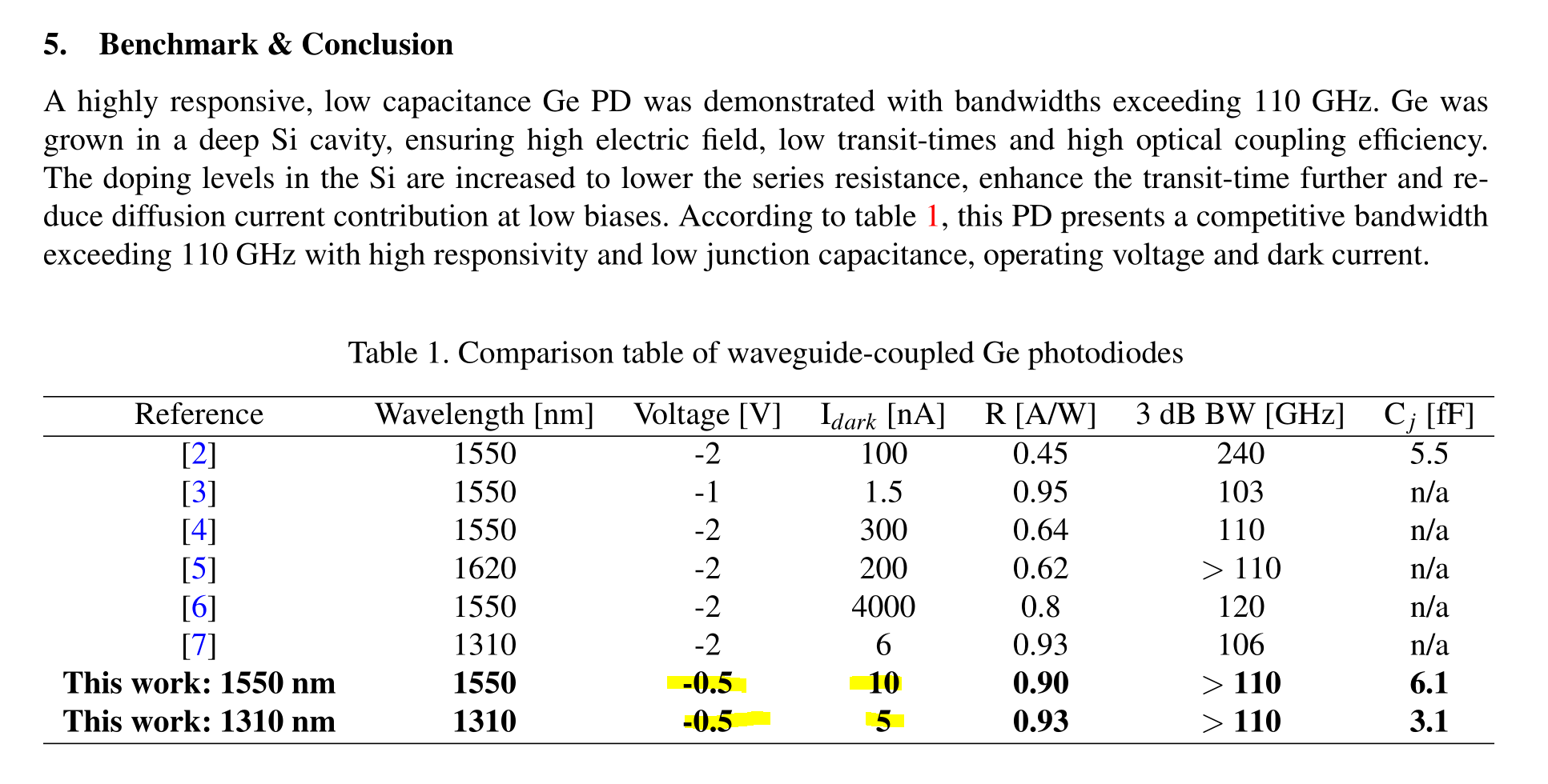
Exceptional dark-current performance as well.
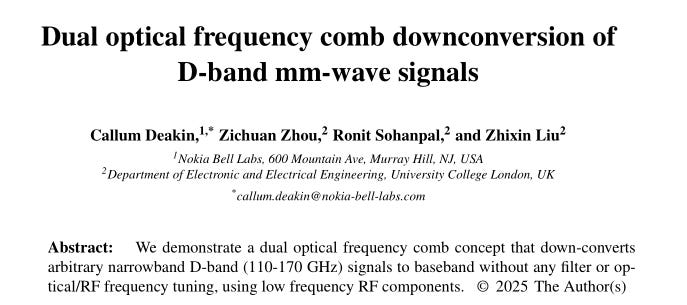
Downconversion with zero tuning? Tell me more.
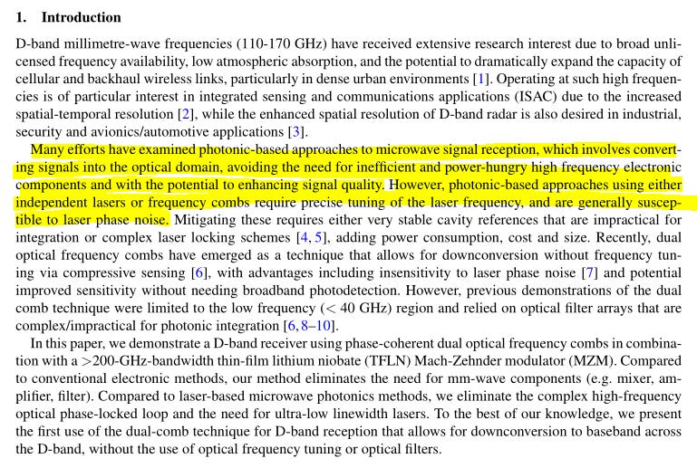
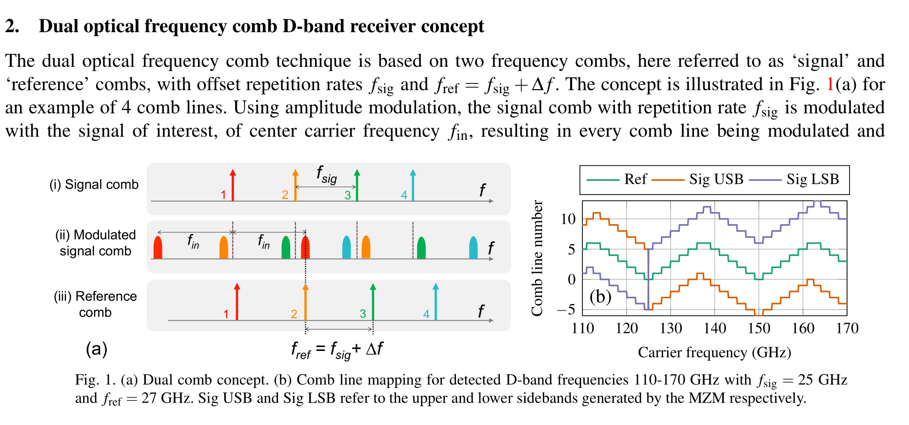
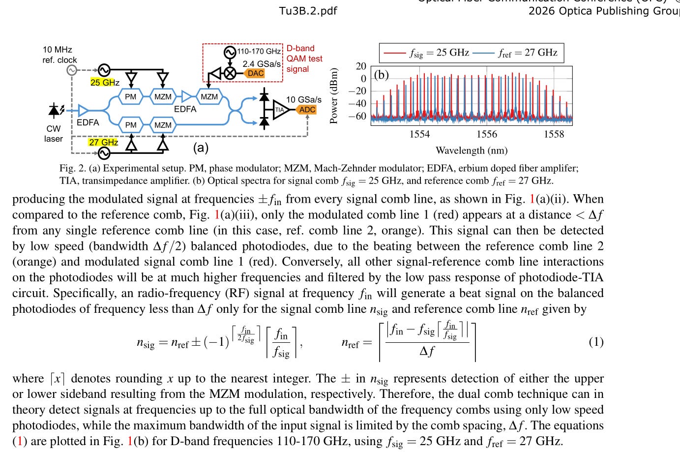
Interesting way of creating a frequency comb. Not clear how they calibrate the spacing.
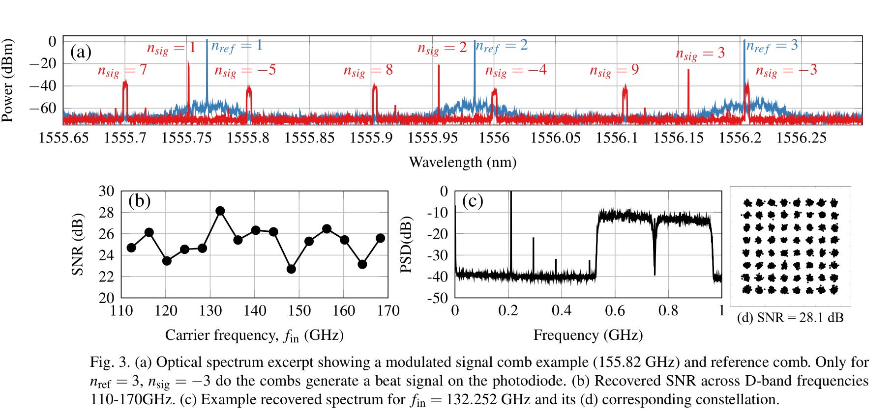
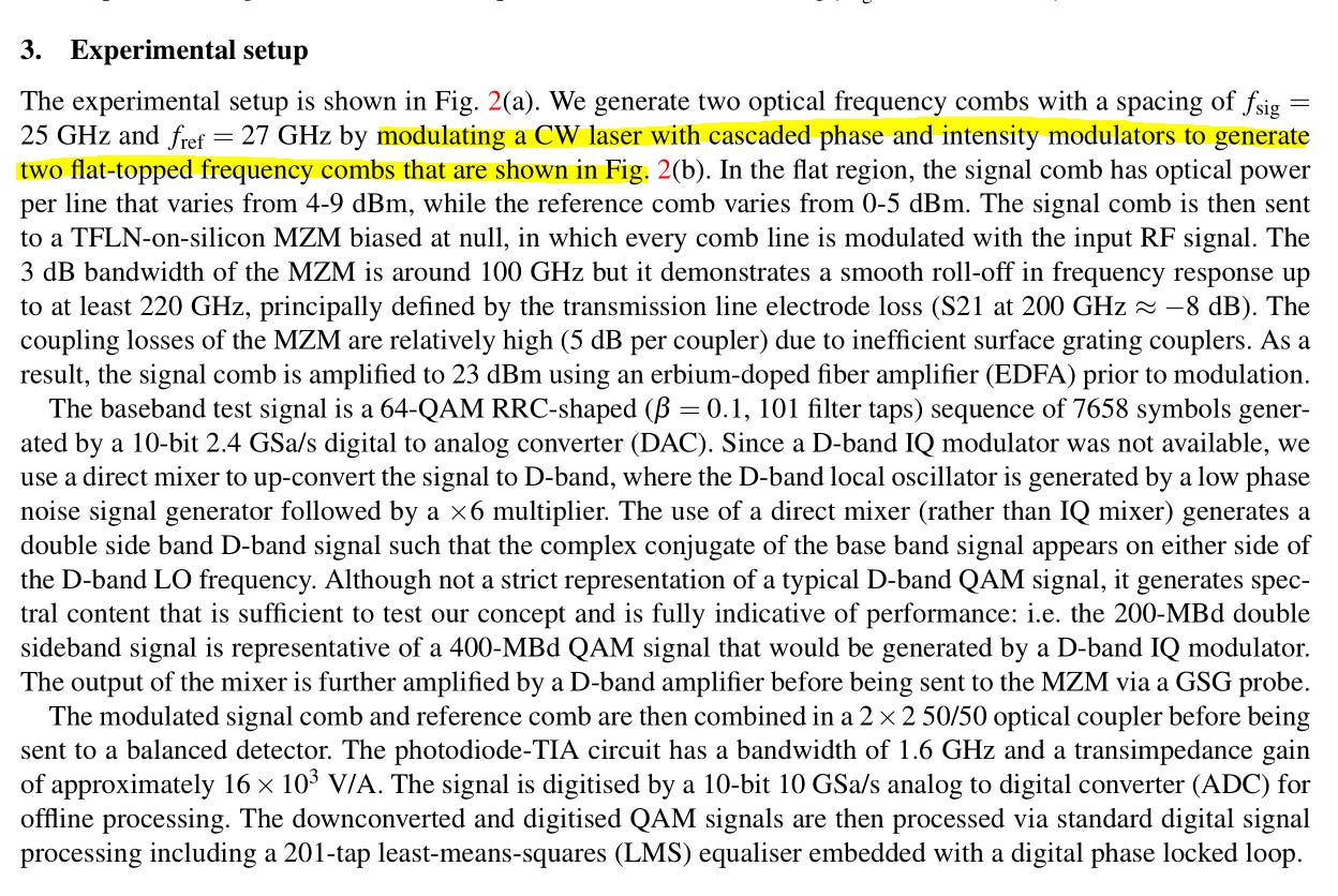
SNR of 28.1 dB on QAM64 is exceptional.
(they are using a 201-tap FFE so it better be good lmao)
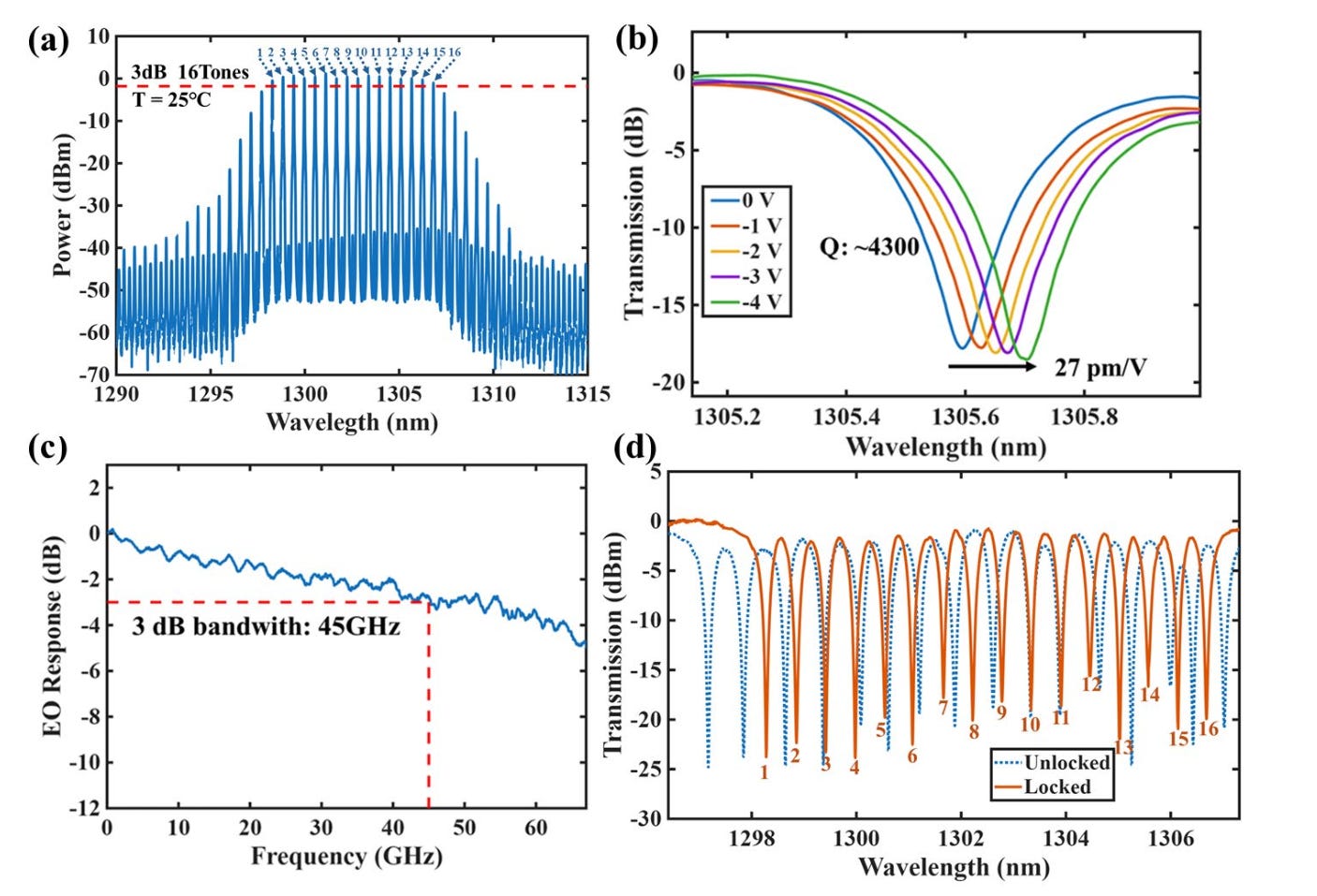
QD comb lasers are neat but yield, power per line, and SMSR are big issues. How are you filtering?
Aha bandpass external filter. So you have no plan for the nasty QD comb laser sidemodes.
(individual channels one at a time… no crosstalk, no SMSR impact… )
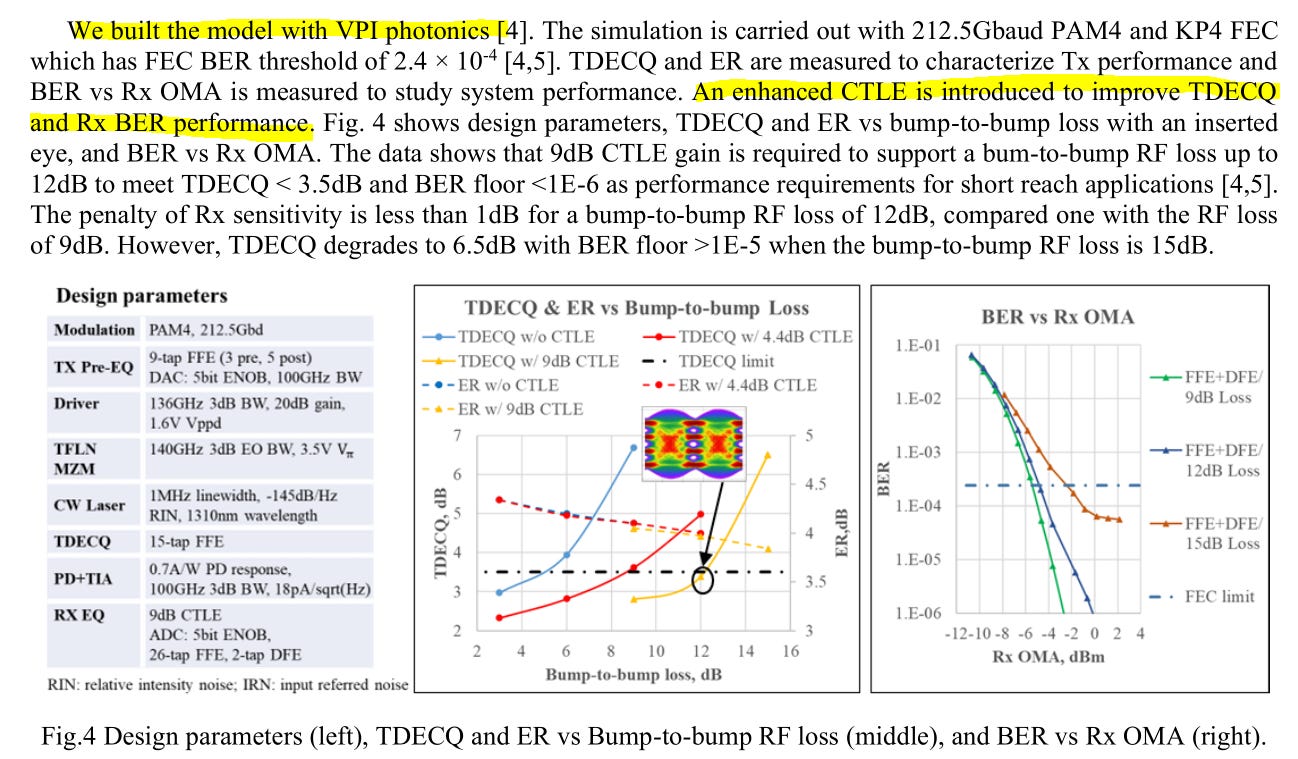
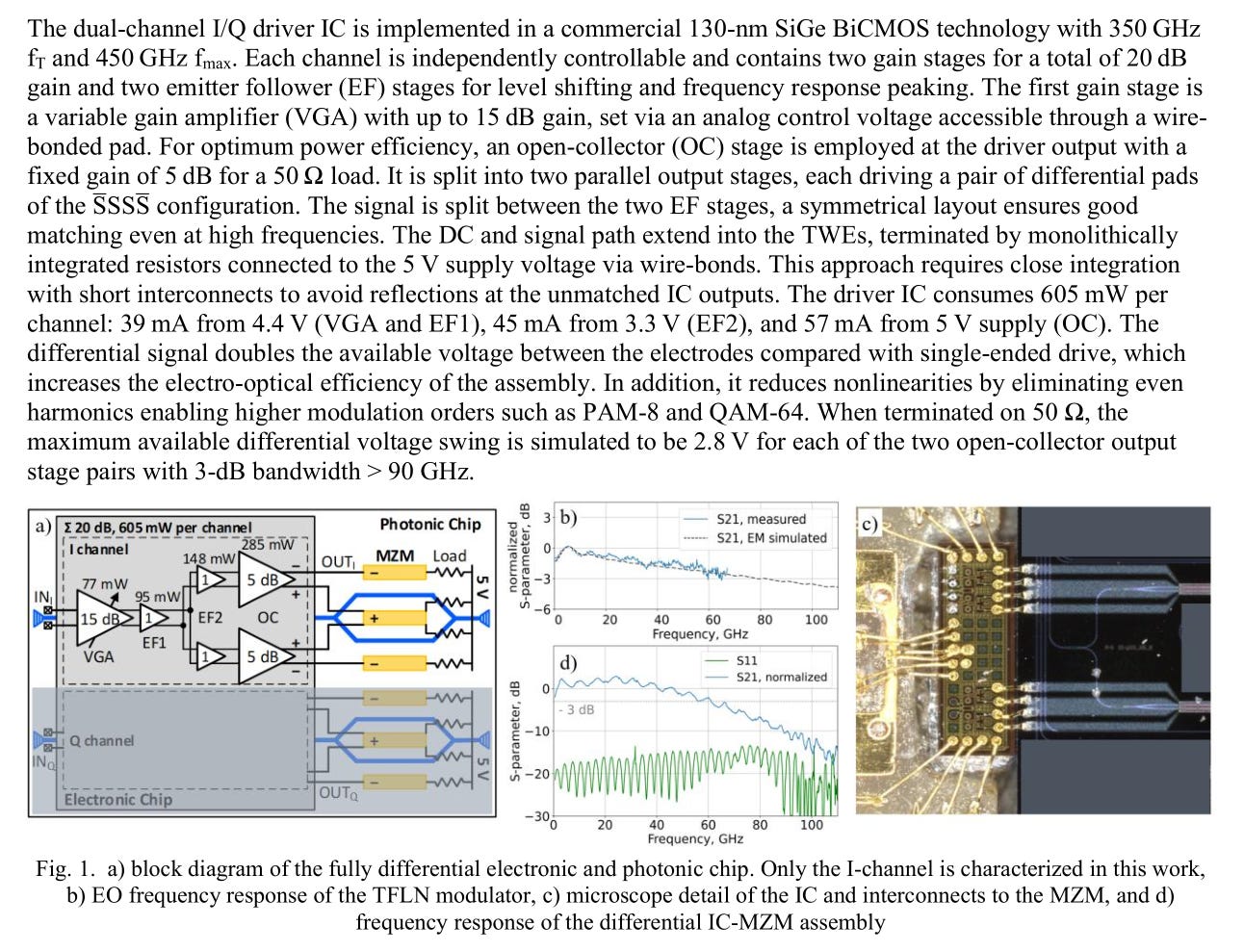
400G linear drive? Fancy CTLE? Interesting…
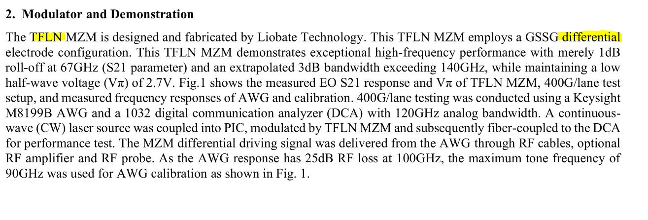
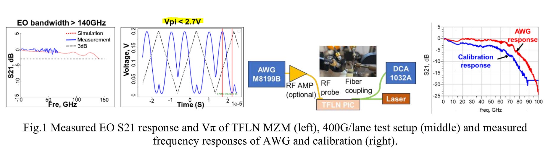
Very low Vpi. Excellent.
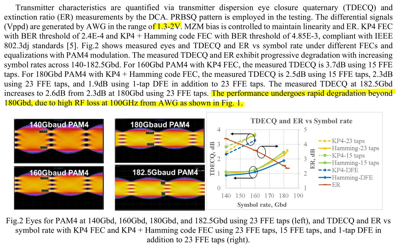
Amazing results.
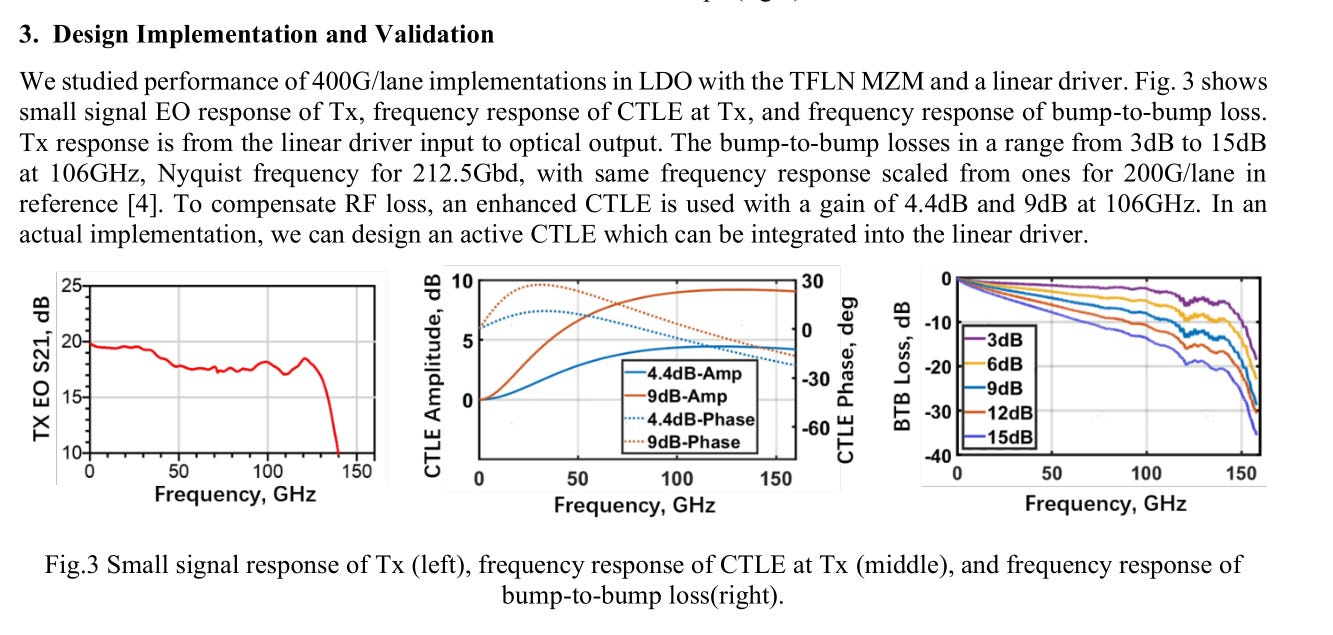
How the fuck did they get 9 dB of gain at 100+ GHz from a CTLE. What black magic is this?
Oh this is just a simulation.
Well it’s neat that they are arguing for a CTLE at the Tx. This is very unusual and their simulations and logic make sense.
Great stuff really enjoyed this one.
Testing one channel at a time (bad) but at least they added gaussian noise to the other channels. In the real-world, there will be some correlated noise across channels but this is a reasonable compromise. Otherwise, testing this would be extraordinarily expensive.
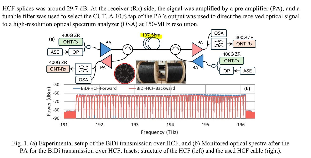
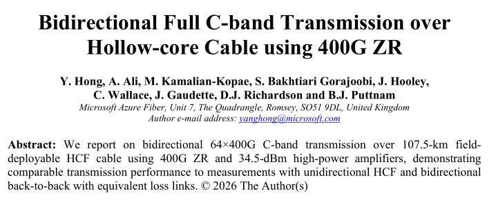
Thats a lot of cable lol.
2.8 watt launch power per channel. Welp, yea this is undersea long-haul. Not sure what I was expecting.
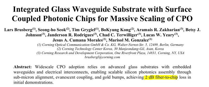
2 dB loss is a lot, but if this strategy massively reduces manufacturing/assembly cost, then it might be worth it.
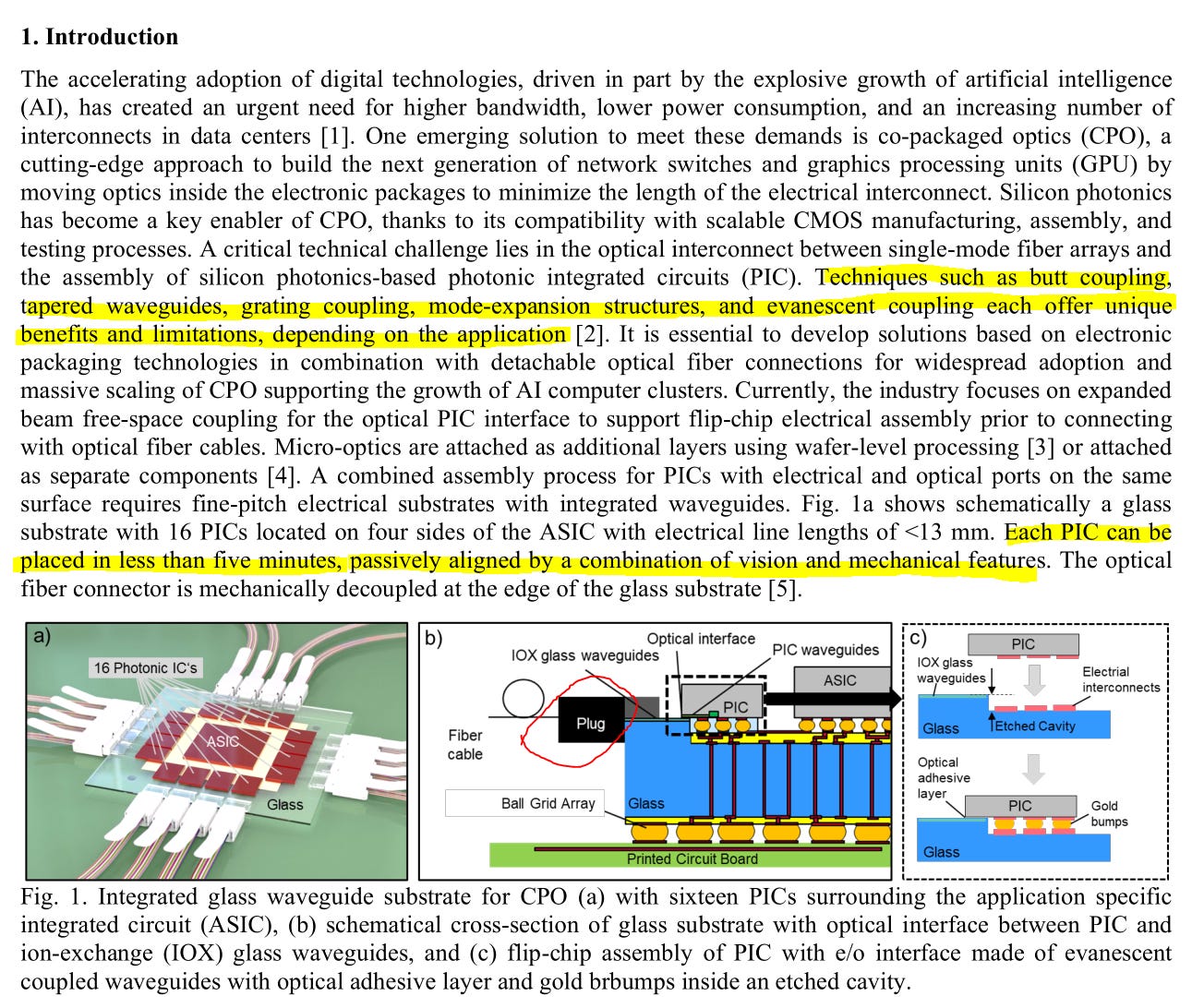
Oh lol the loss is much worse. 2 dB is the best case scenario.
Also the impedance variation across electrical bumps is… unacceptably high.
Very cool but far from being economically viable.
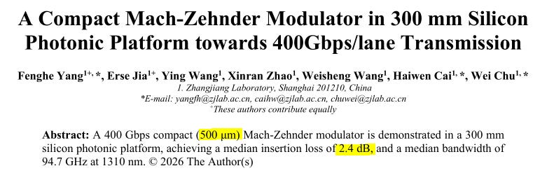
2.4 dB insertion loss is indeed quite low. Normally MZI insertion loss is 5 dB ish.
Then again, normal MZI modulators are 1000-2500 micron in length.
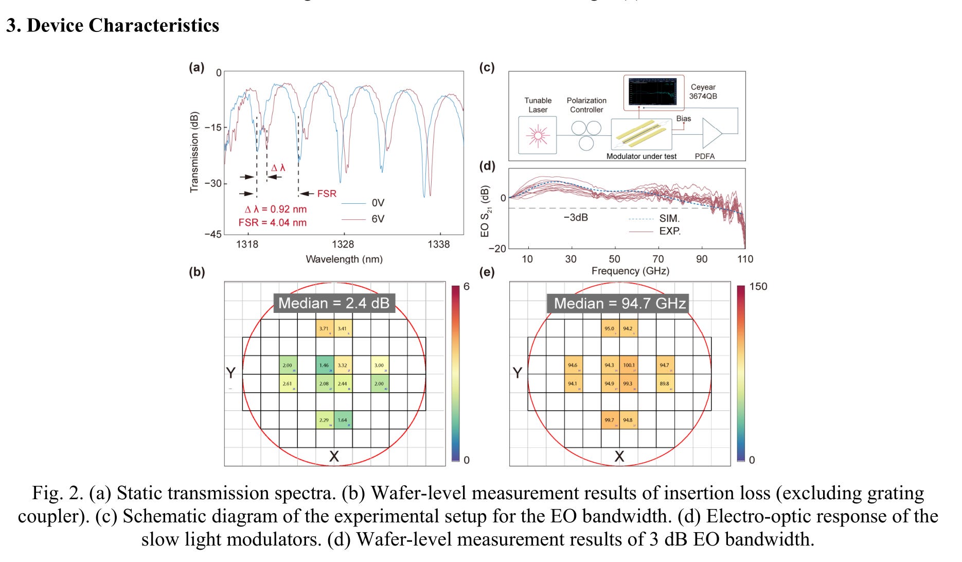
Pretty good. Glad they showed waver-level data.
Exceptional results.
I have no clue how they achieved such good results. If anyone who knows physics things can explain, please send me an email.
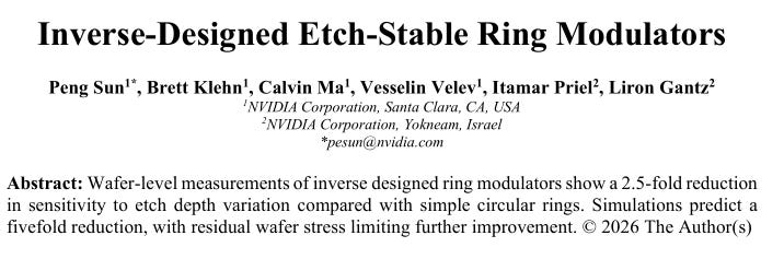
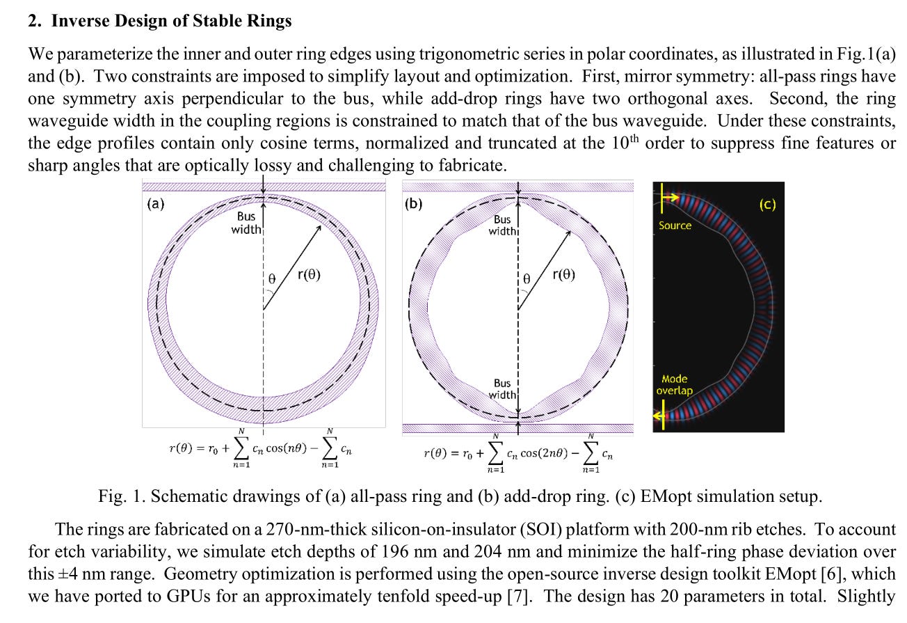
Inverse design is a computational method that uses simulations to work backwards. It typically leads to weird shapes.
The problem with inverse designs is they often violate PDK DRC, violently.
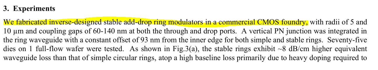
I am 95% confident the “commercial CMOS foundry” that fabed these weird inverse-designed rings is NOT TSMC.
Don’t get me wrong, inverse design is very cool and sometimes it even works in commercial applications, but more often then not the weird shapes aggressively violate design rules, leading to the foundry saying “no we absolutely will not accept this GDS go away.”
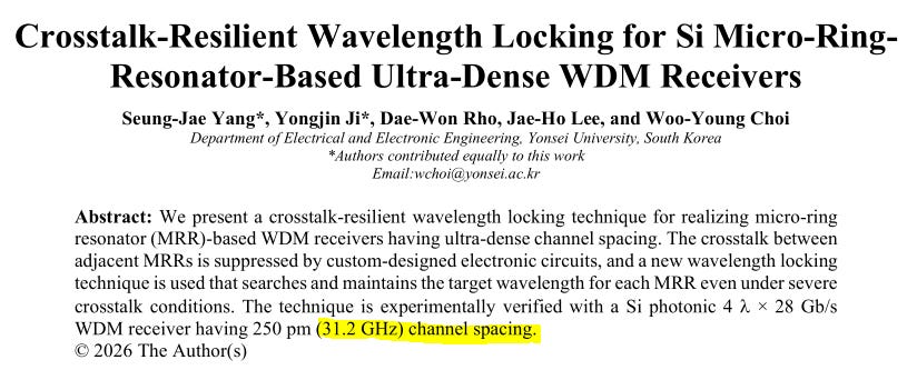
Locking rings at < 100 GHz channel spacing is incredibly difficult.
Here is the normal locking method. (baseline)
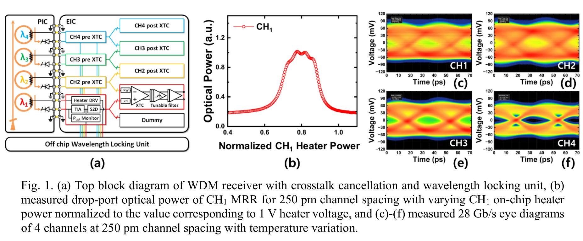
And here is the fancy derivative sum method.
Massive improvement!
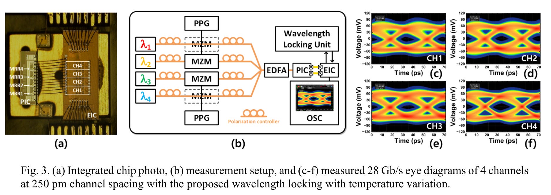
Hmmm AMD CWDM mux with MMI. Interesting…
Why would you need this mux if you are using Ayar Labs rings? Is this the backup plan?
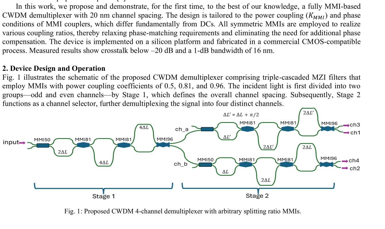
This diagram screams “massive insertion loss” but ok lets wait.

Guys where is the insertion loss. Sure you got good rejection of unwanted bands but come on you cant leave IL out.
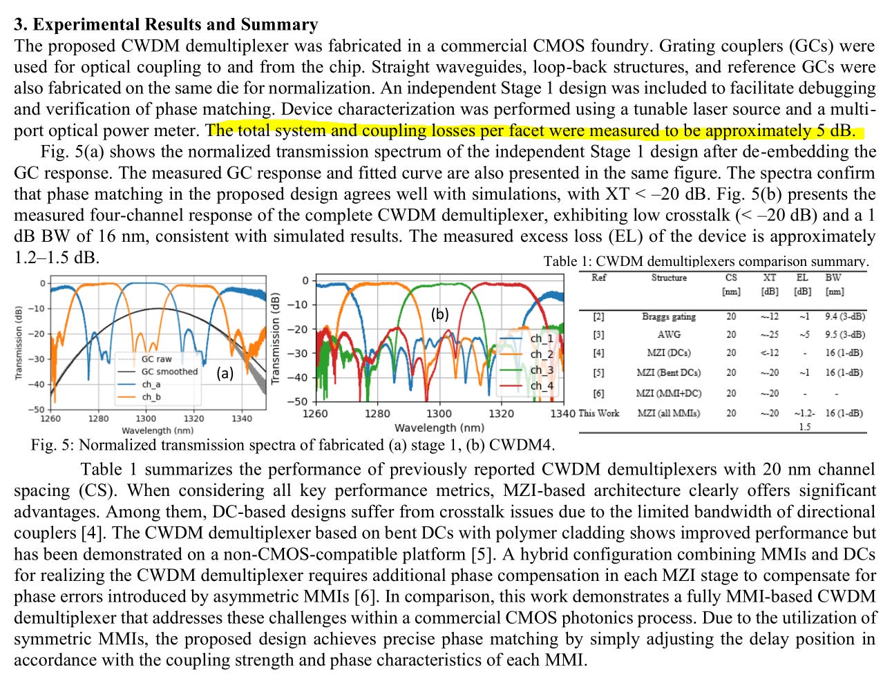
Honestly not bad. Way better than I expected.
Dare I say… 5 dB insertion loss of the entire system is pretty good.
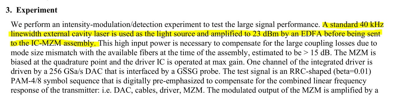
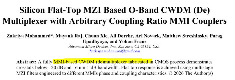
“Standard” 40 KHz linewidth laser lol.
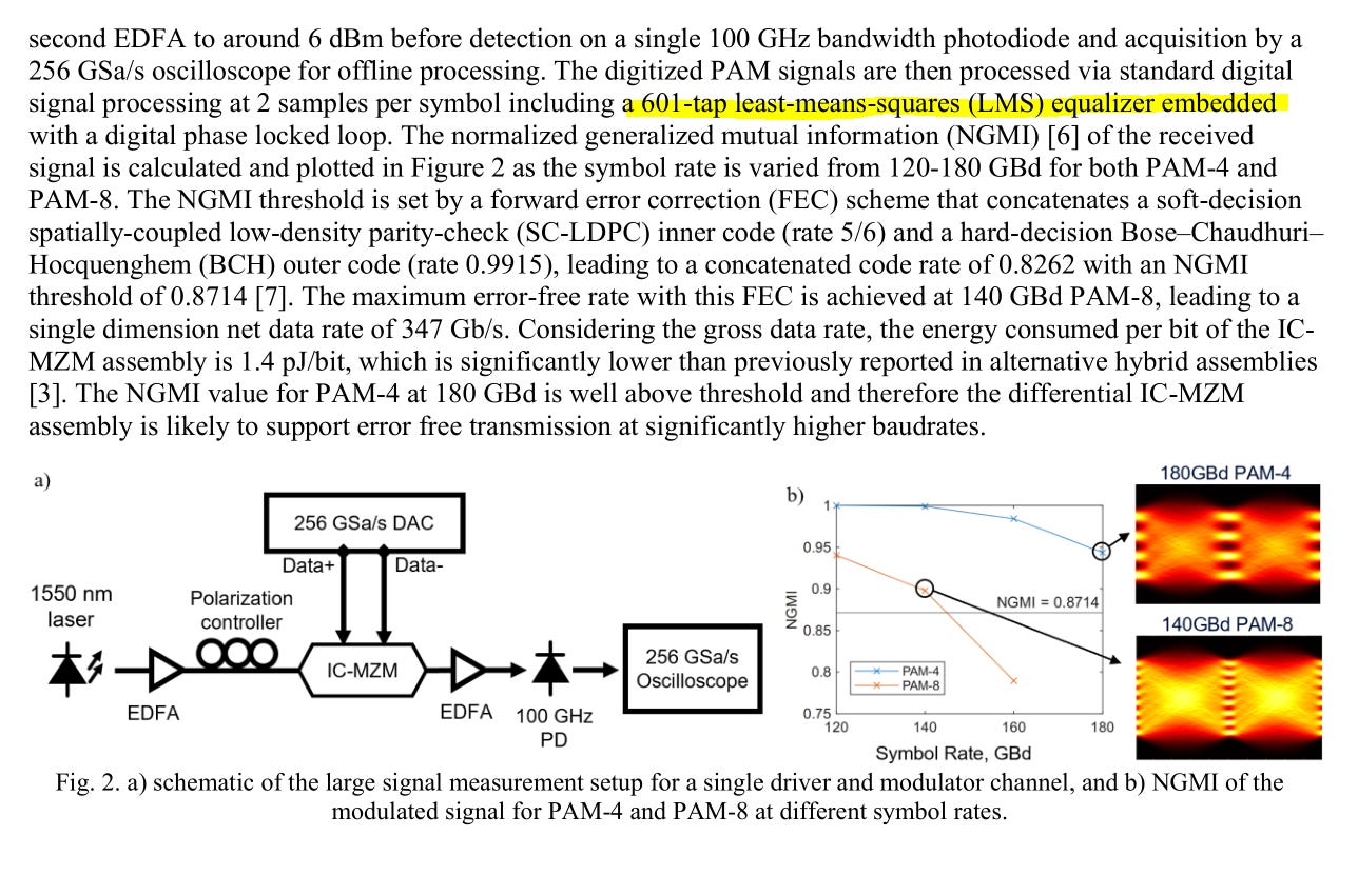
“standard digital signal processing”
» 601-tap FFE

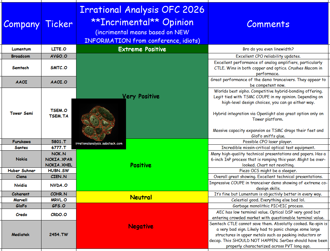
[3] Public Markets: Re[tail]-Tard and Pod Monkey Summary
Are you so brain-damaged you need a color-coded chart with simple words to make investment decisions?
This section is for you.
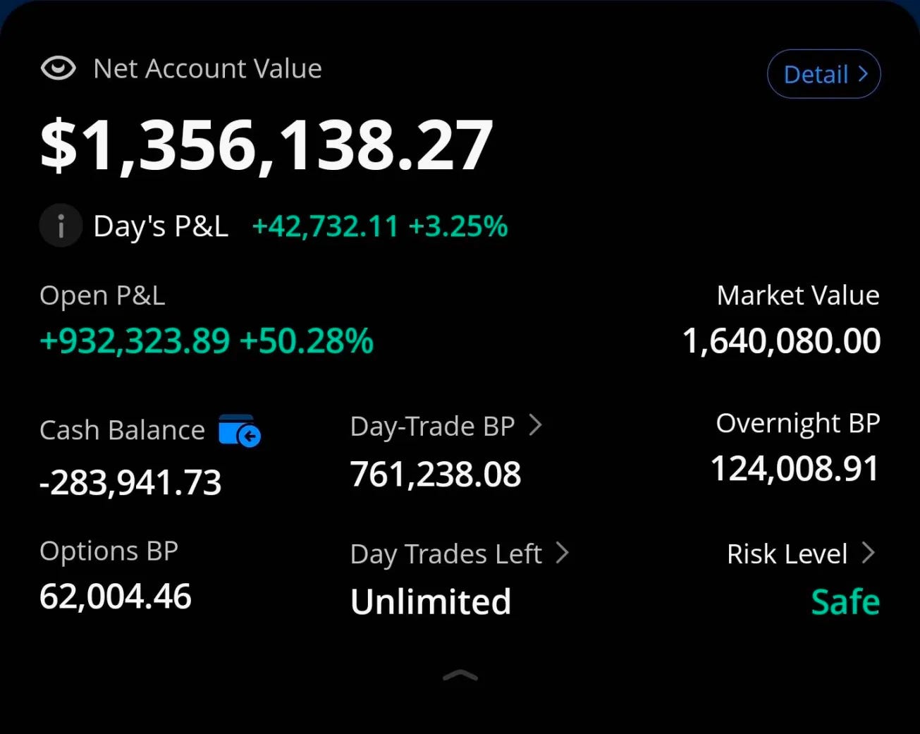
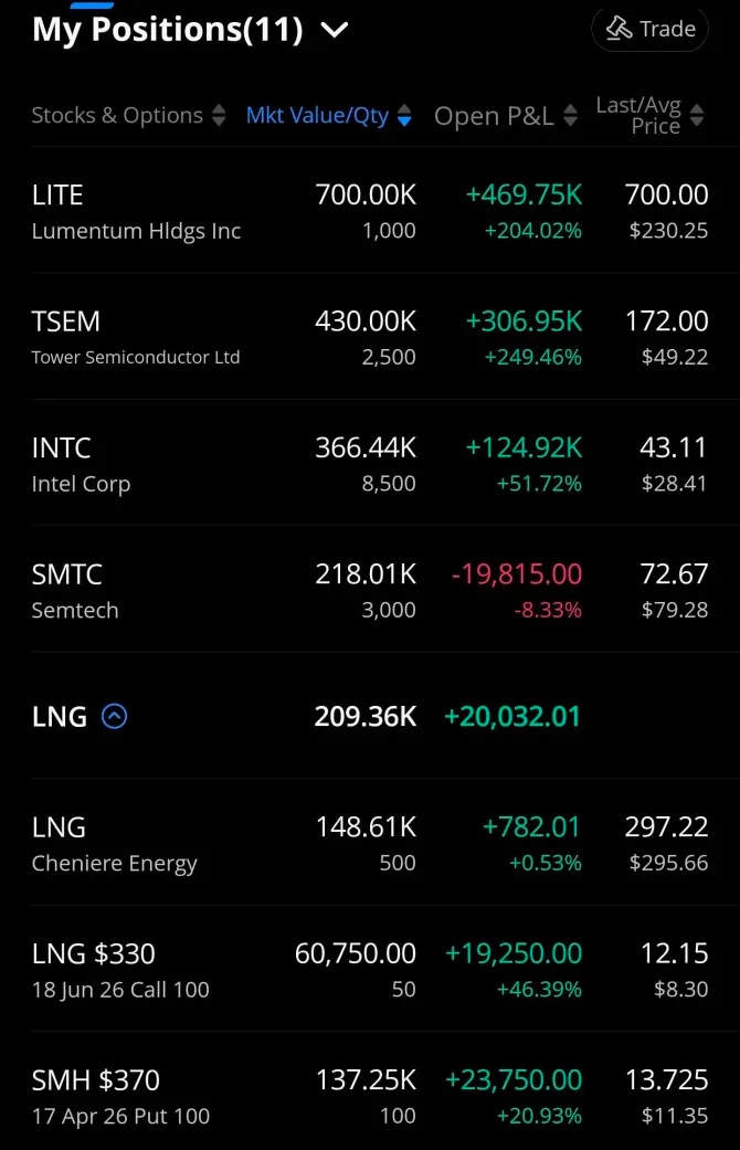
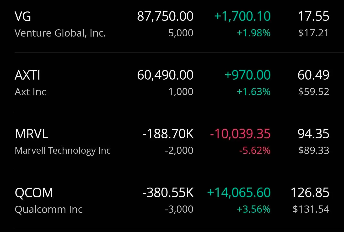
[4] Trading Account 3/27/2026 Snapshot
I will be publishing full trading record (all transactions, monthly account statements) for Q1 2026 next week. Will also re-build my shit manually updated spreadsheet that consolidates the long-only accounts.
Are you having fun with the increased levels of KABOOM in the middle east yet?


Check out my tourist overview of liquified natural gas.
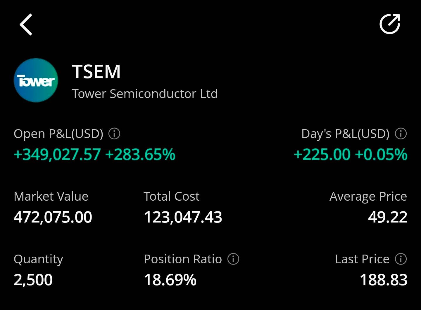
Here is the trading account at the time of writing.
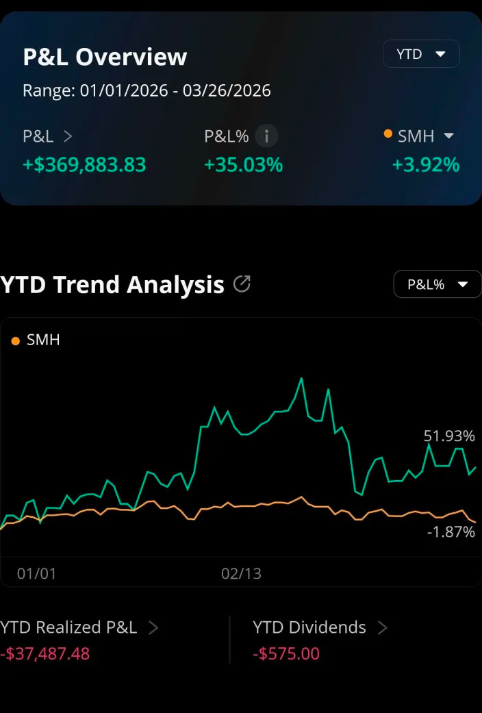
Barely meeting my performance target of +30% over SMH/benchmark.
thank you for your insight!
How do you find the time to write a textbook post?
Impressive, learned a lot, you keep getting better. Thanks!
Question: I understand that linewidth / coherent laser is important for long line DWDM where spectrum is crowded. But why does it matter for simple fiber systems? Noise floors of even 20dB in the laser due to line width seem literally lost in the noise compared to systems designed to recover very low BER at just 6dB or so S/N. If the main market of a high-power laser is to divide it over 8 or 16 lossy modulators with no spectrum bounds isn't a MHz of bandwidth just fine? What am I missing here about needing squeaky clean lasers to drive a signal that is going to be drowned in far more noise by the time it gets to destination?