
ISSCC 2026 Irrational Recap
Incredible Nvidia and Celestial/Marvell Presentations

Irrational Analysis is heavily invested in the semiconductor industry.
Positions will change over time and are regularly updated.
Opinions are authors own and do not represent past, present, and/or future employers.
All content published on this newsletter is based on public information and independent research conducted since 2011.
This newsletter is not financial advice and readers should always do their own research before investing in any security.
Feel free to contact me via email at: irrational_analysis@proton.me
Some really cool stuff with high-impact investment implications.
Summary for pod monkeys who want to trade at market open:
Nvidia:
They are crazy, in an admirable way.
On the path to achieving the holy grail of interconnect technology.
Very encouraging results.
Celestial/Marvell:
Excellent results.
100% of Marvell valuation should be derived from Celestial.
MediaTek:
General weakness and suspicious behavior.
Semianalysis is completely wrong on their TPU call.
Only way for MediaTek to be viable is via Semtech linear equalizers.

Contents:
Nvidia
Celestial/Marvell
MediaTek
Trading Account Update
[1] Nvidia
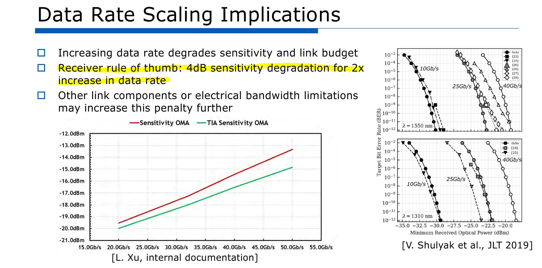
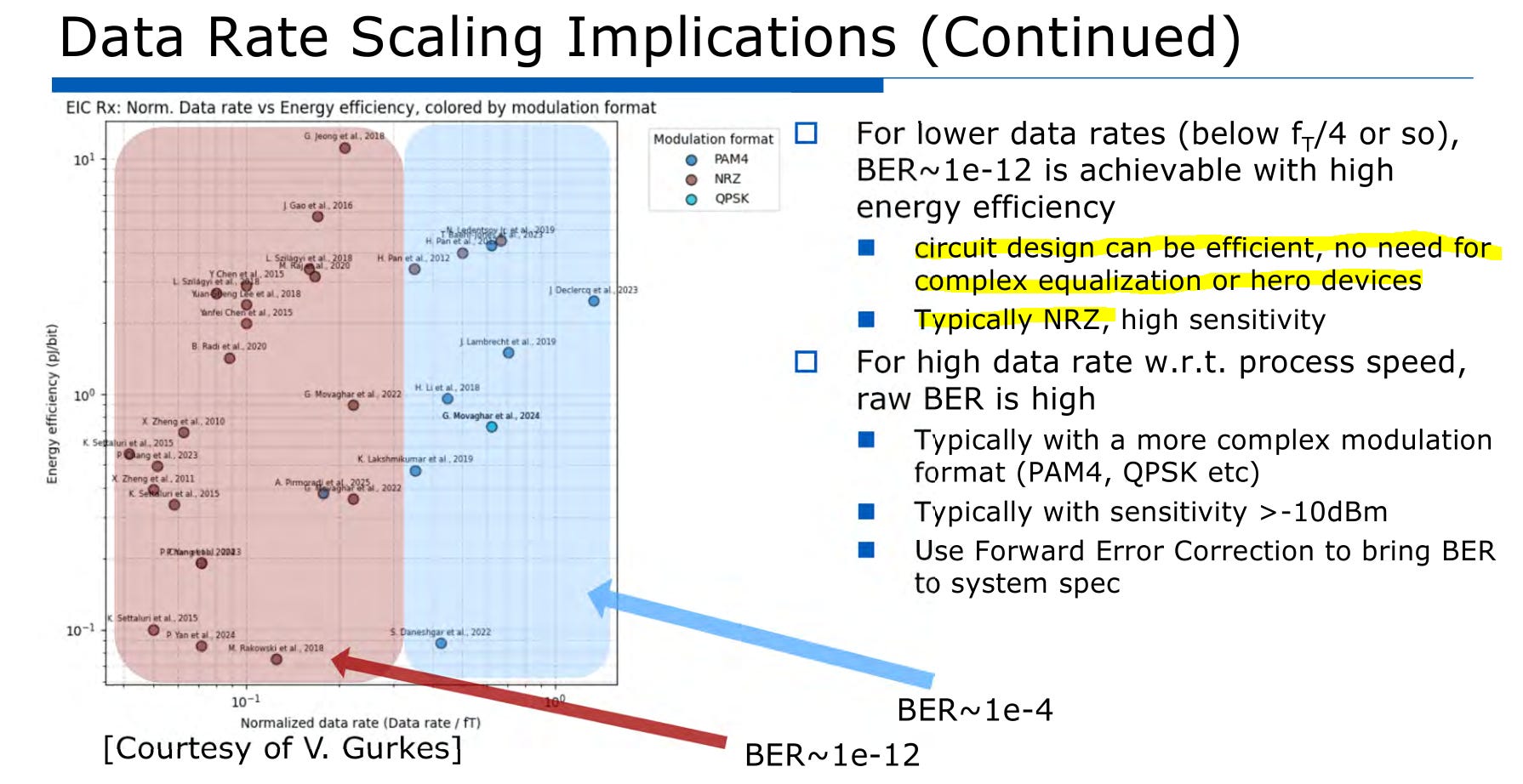
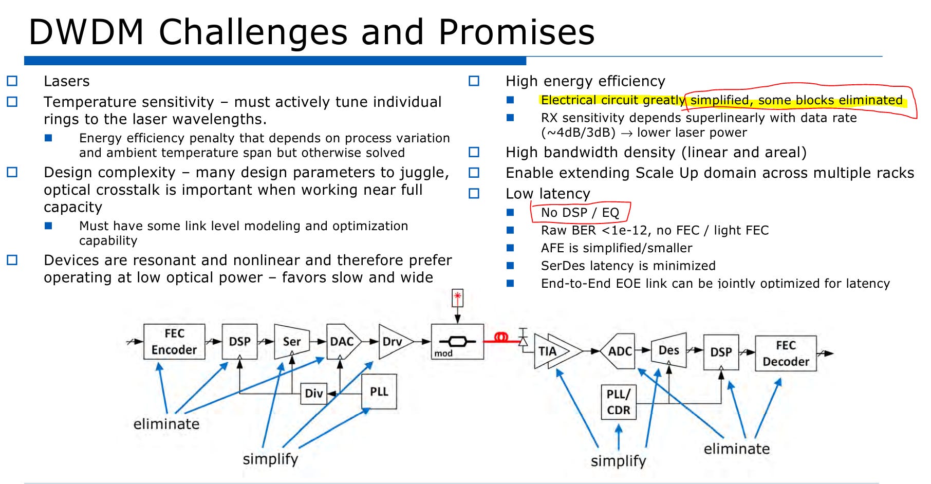
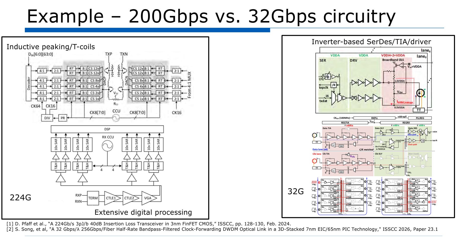
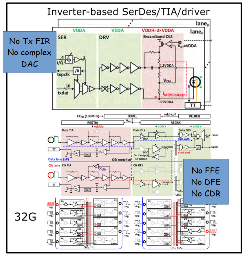
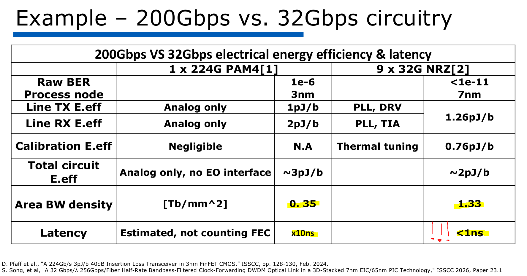
Nvidia is arguing that a slow and wide approach (many 32Gbps NRZ lanes) is much better than standard 200Gbps PAM4 lanes. Main objectives are reducing power and latency.
The arguments are very compelling. This presentation was more of a high-level “why we are doing this”.
Now let’s go to the incredible results.
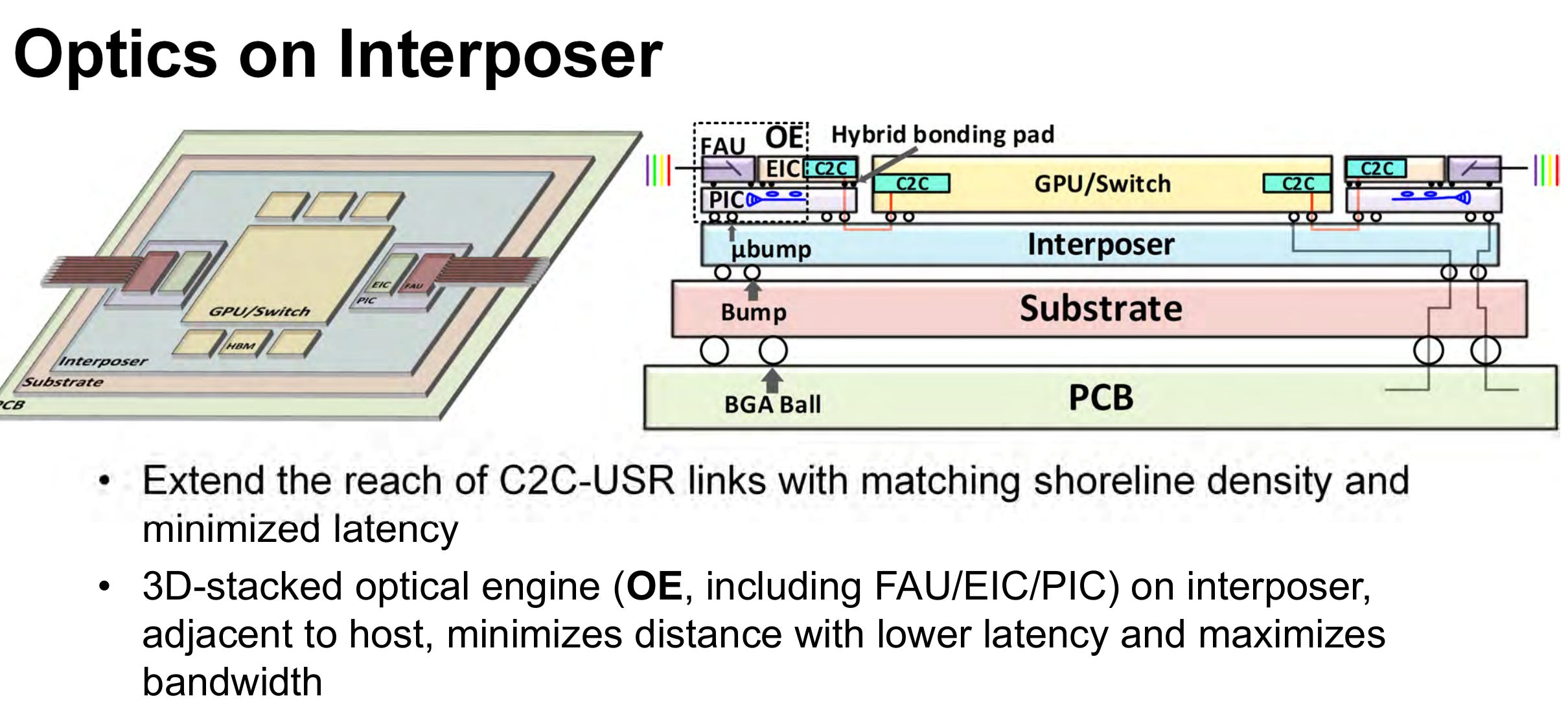
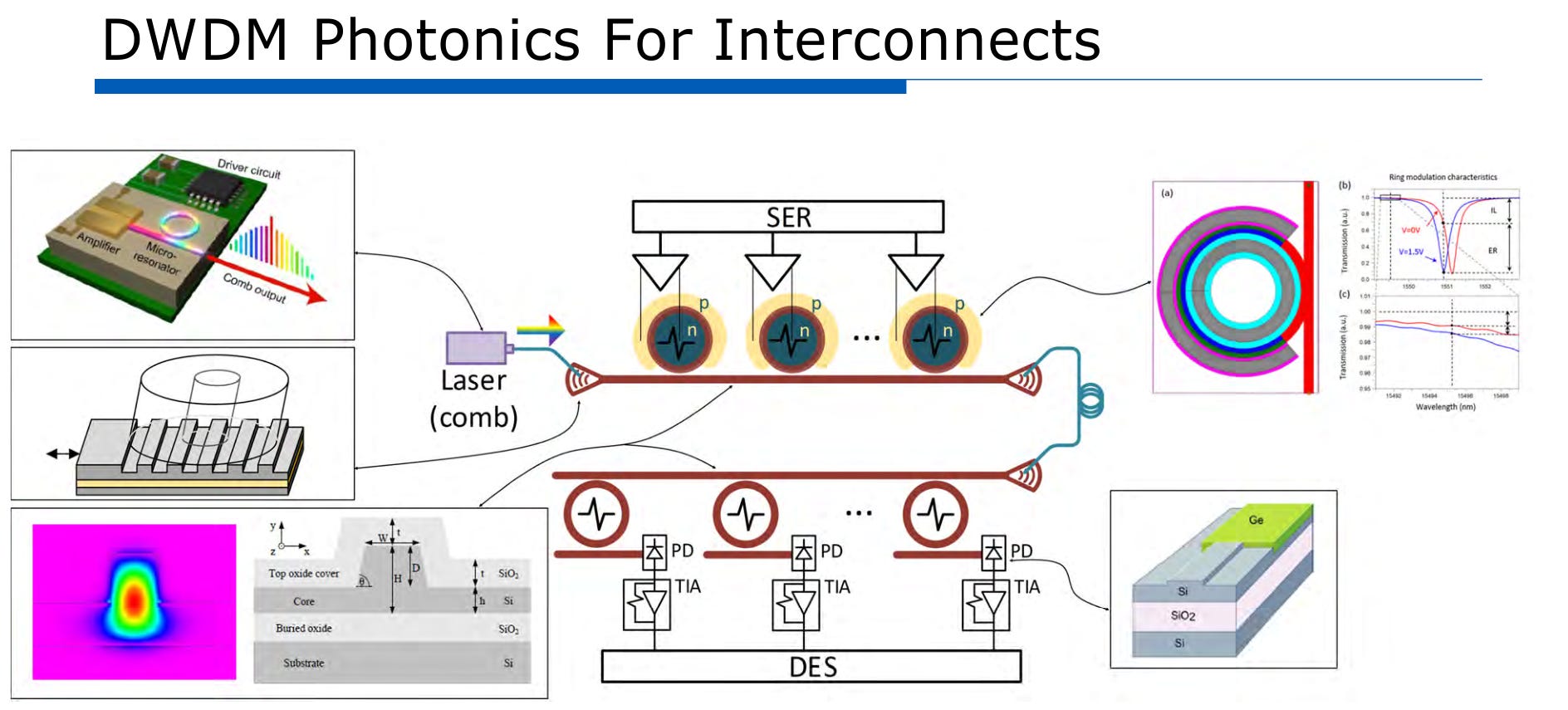
This is using TSMC COUPE. An optical extension of NVLink D2D.
D2D PHYs (UCIe style) rely on clock forwarding. Sending the clock optically is the main challenge.
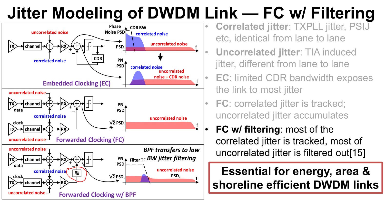
They are using a bandpass filter to clean up the forwarded clock. Designing this filter to be resistant to PVT must have been challenging.
Surprising that chromatic dispersion delays matters in this case. System is very sensitive!
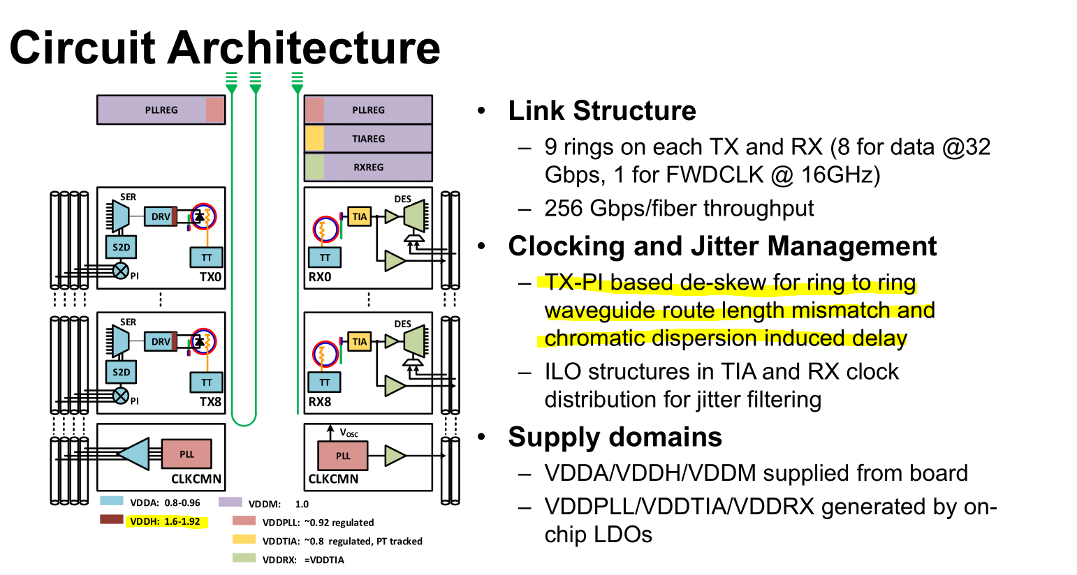
It is common for Tx and Rx to have a phase interpolator. They cut the Rx PI to save on power probably.
Also VDDH is quite high. Not sure if this design can pass HTOL?
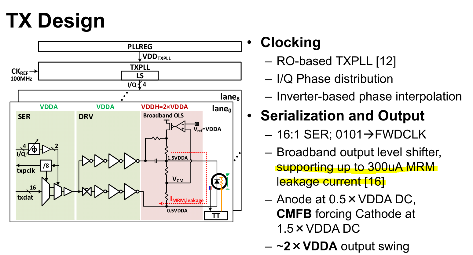
Seems like a lot of leakage?
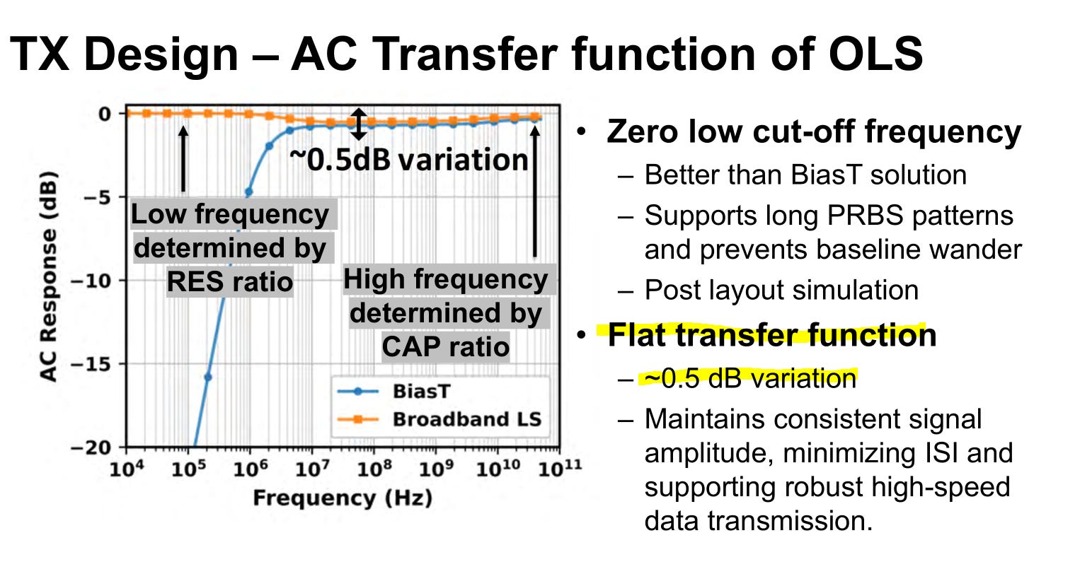
Beautiful transfer function for Tx. Super clean.
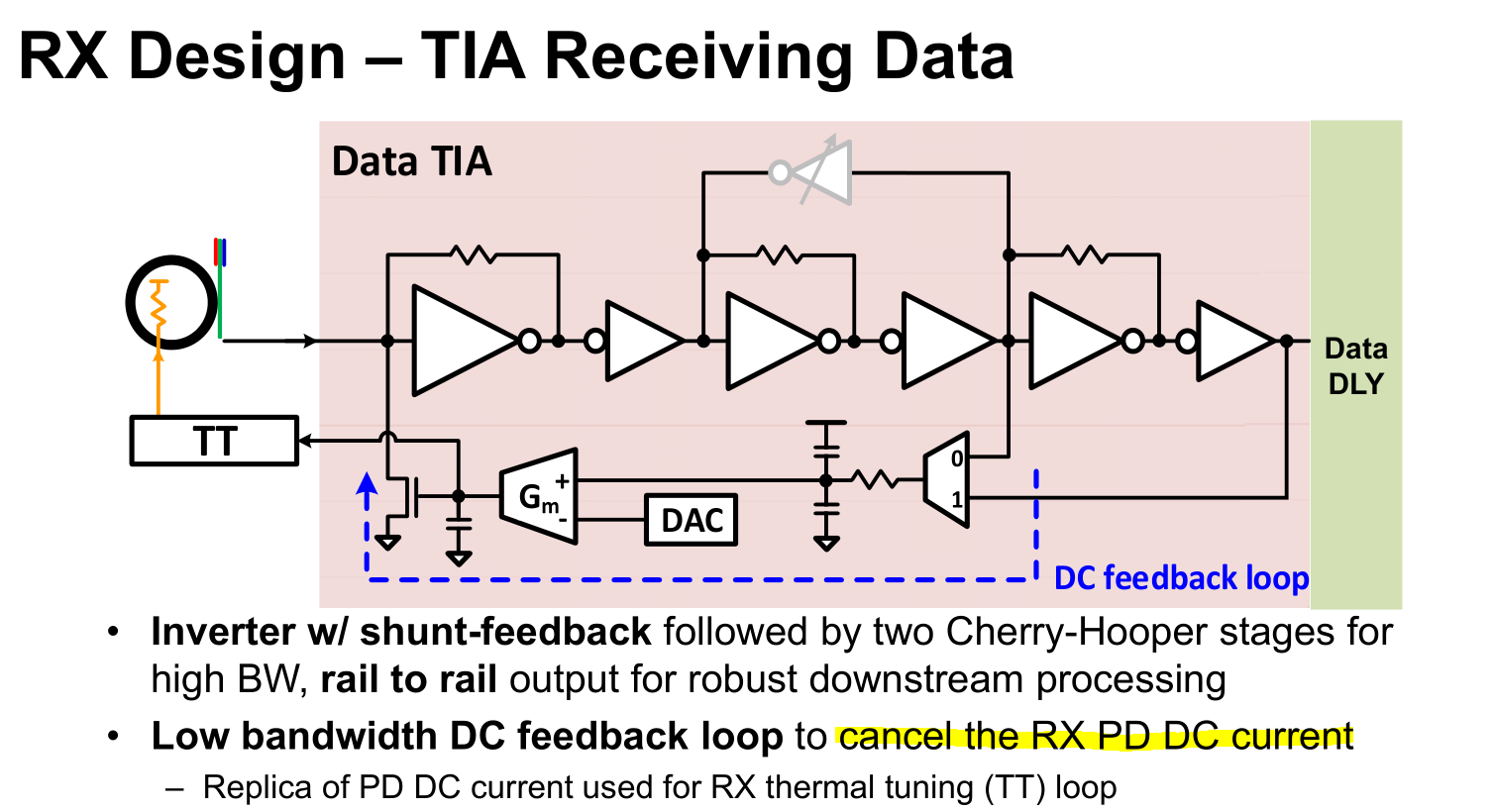
Clever dark current mitigations.
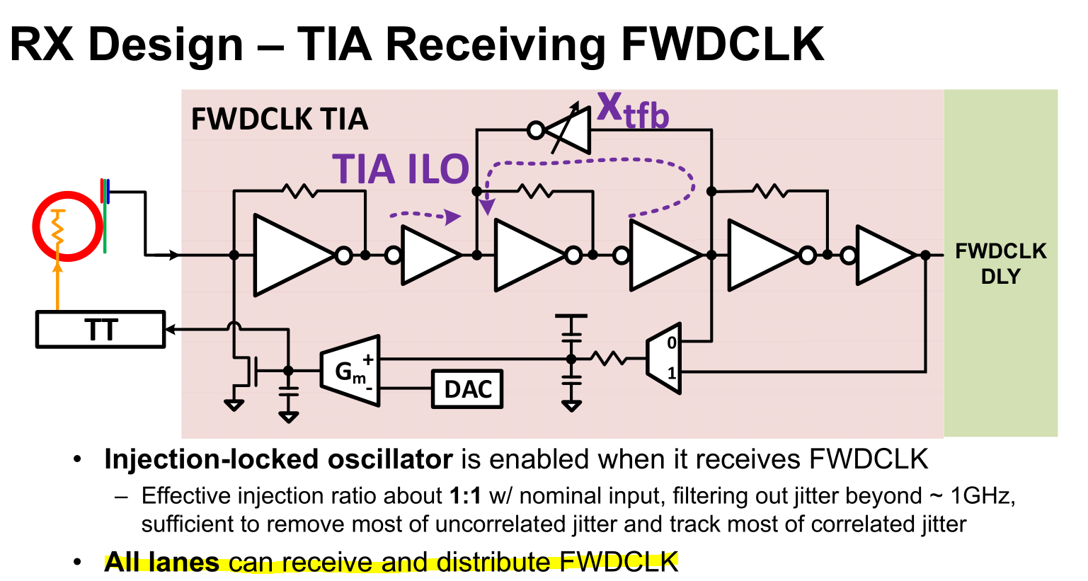
Very very interesting that all lanes can act as the clock forward. This burns a non-trivial amount of area. This must be for yield. Performance must vary a lot based on which lane is sending the clock.
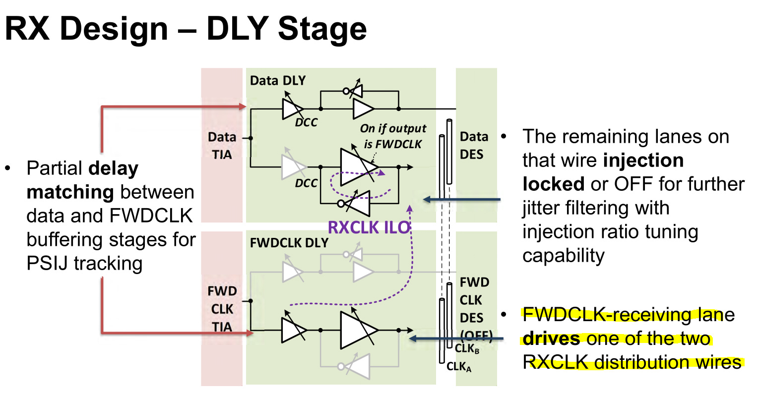
Strange that there are two RXCLK distribution wires. There must be a reason for this. Another yield hedge?
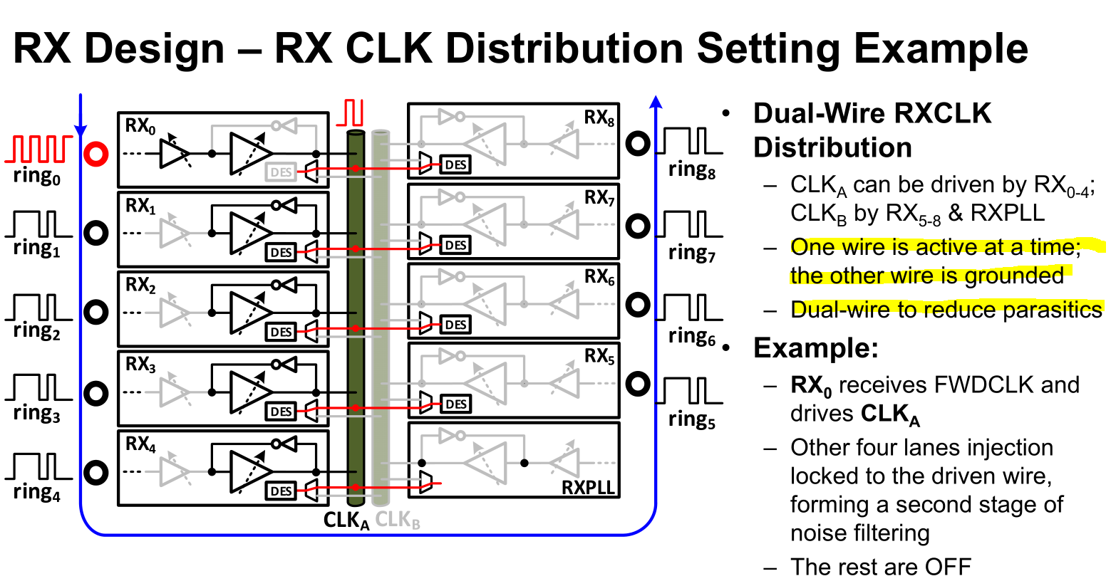
Oh they wanted to minimize wire parasitic. Segment grids.
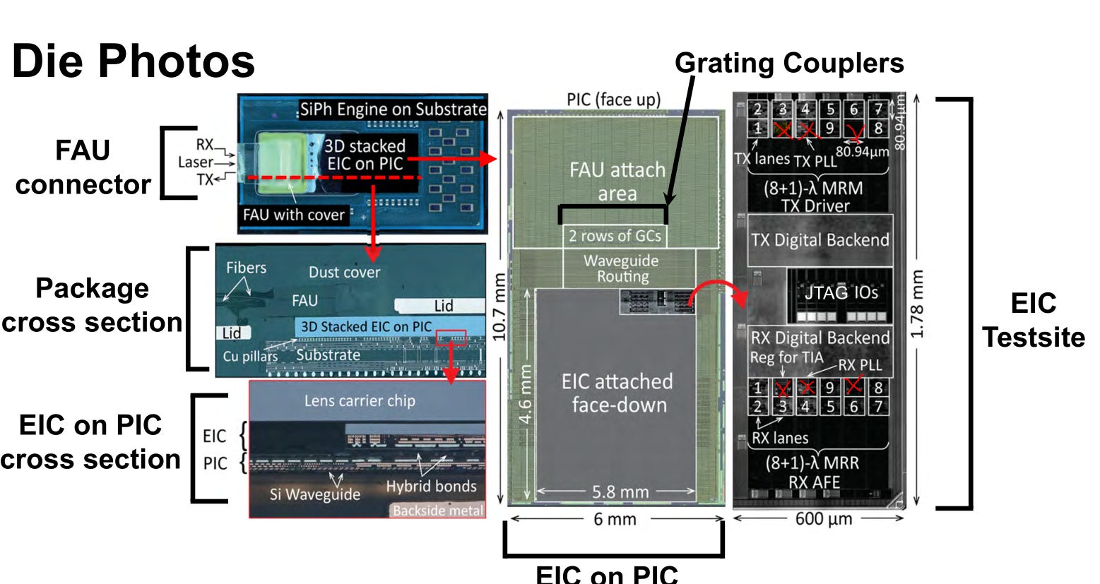
Curious if they have three extra lanes for yield. Marked them with red X.
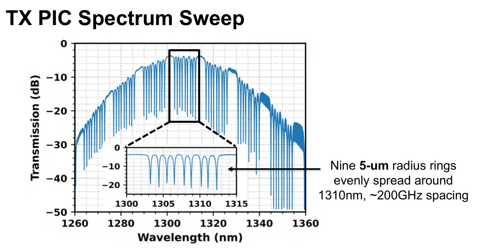
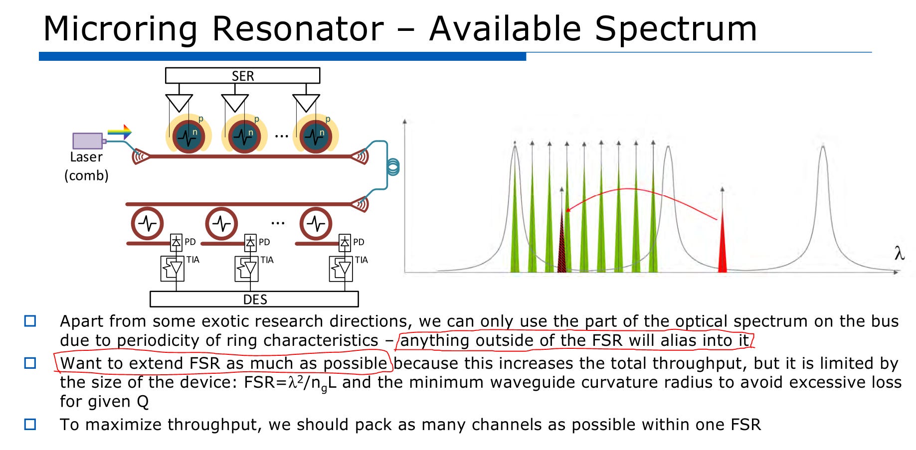
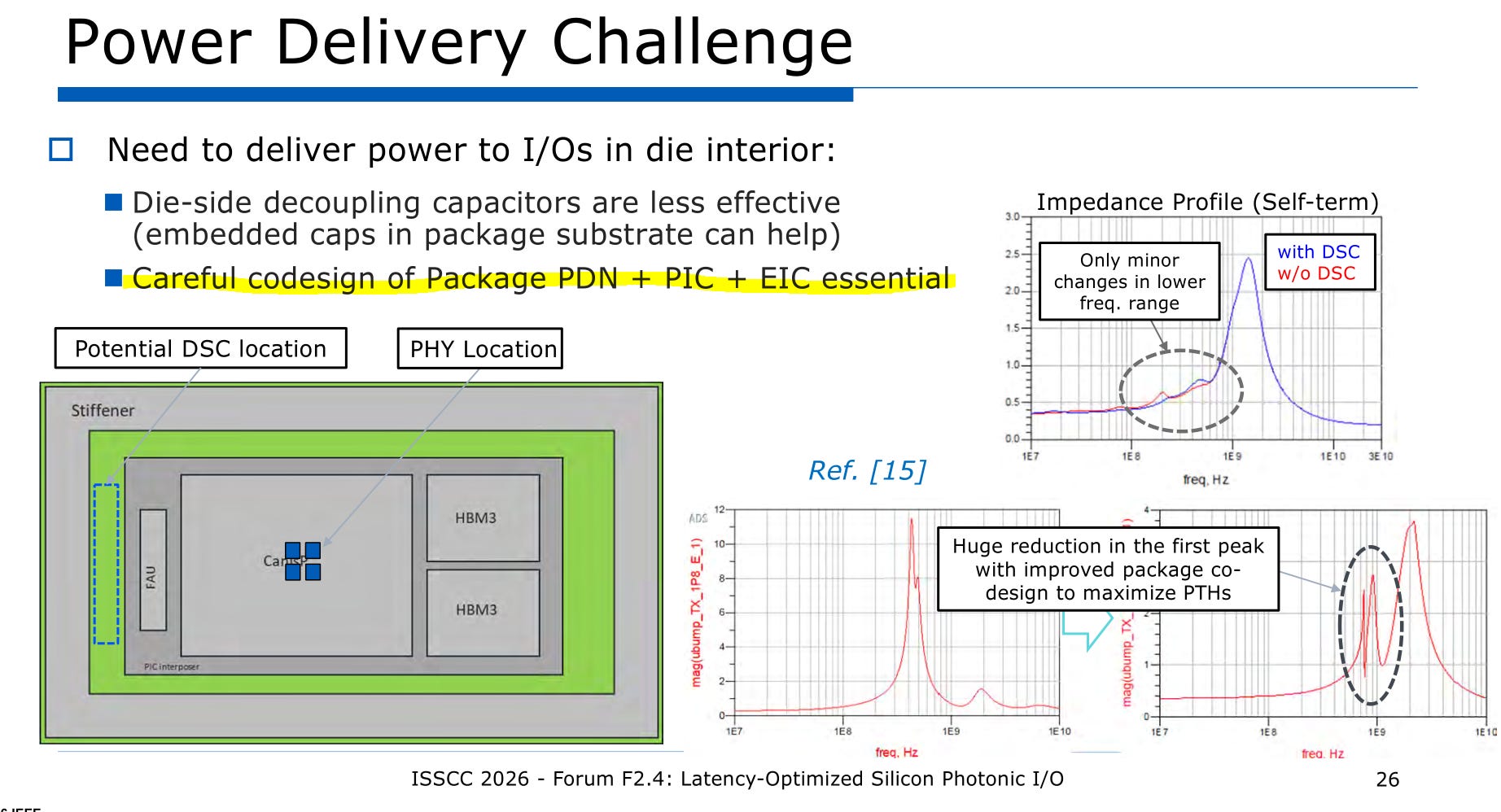
This slide is very important because it shows one of the main issues with ring modulators.
Periodicity.
Any junk outside of the black box in the center can show up. Optical bandpass filters are very difficult to make.
Additionally, notice two key attributes of the system…
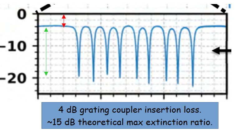
Grating couplers are wonderful for manufacturing but induce a bandwidth and power penalty. Losing 4 dB just from coupling is painful. Edge coupling is more 1-1.5 dB if done right but much more expensive and scales poorly.
The ring extinction ratio could be 15 dB if modulation aligns with the resonance. Reality is very different. Will get to that shortly.
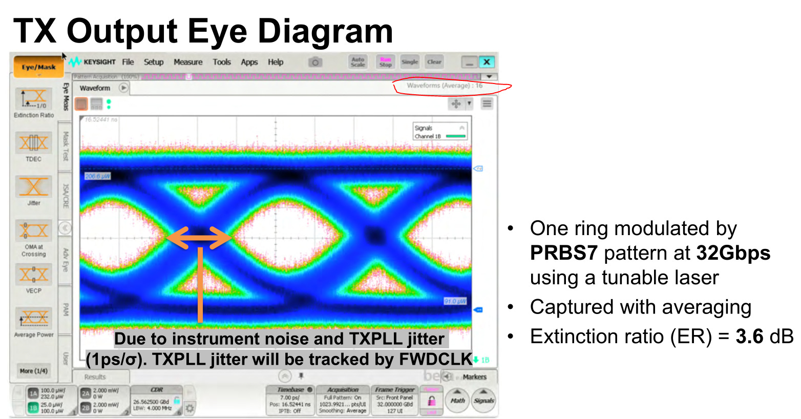
Averaging should never be used in this context. Scope averaging is for getting noise floor.
Anything less than PRBS13 should not be used.
Extinction ratio of 3.6 dB is not great. Most non-ring modulators can hit 5-9 dB ER.
Bluntly, this Tx eye is not impressive. They seem to have no margin on amplitude noise.
However, later results are incredible. Their receiver design is KICKASS.
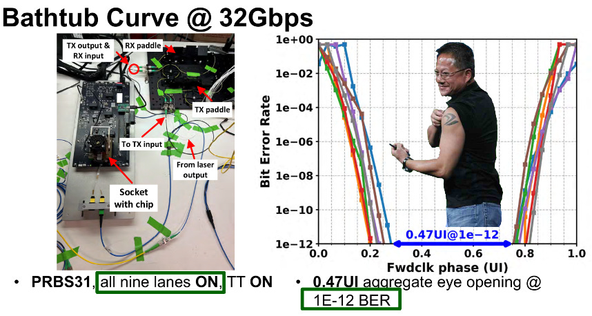
This is truly incredible.
They don’t need PRBS31. PRBS13 good enough but sure flex why not.
1e-12 on all lanes WITH ALL LANES ACTIVE AND DUMPING ELECTRICAL AND THERMAL NOISE INTO EACH OTHER IS FUCKING AMAZING.
The lanes are also remarkably consistent. Not major outliers. Indicates the design is robust to PVT.
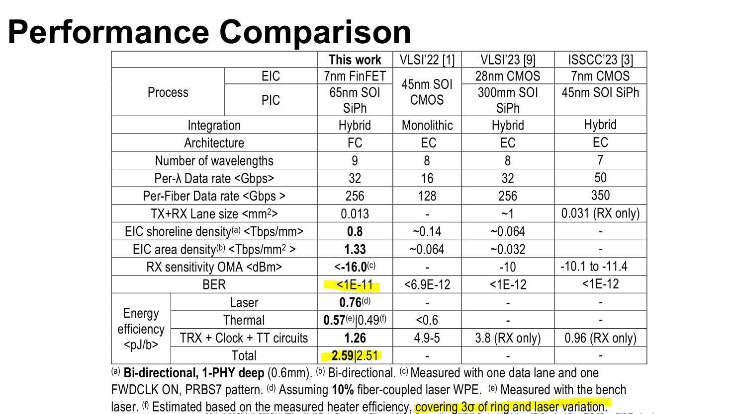
2.6 pj/bit with ~1 ns latency is incredible.
These crazy people actually did it. They sort of acheived the holy grail of communication systems.
Clock-forward die-to-die PHY over optics.
Extending the reach of something designed for < 2 mm of channel length to potentially 100+ meters.
This is where all datacenter links will eventually go. Its historic.
I think Nvidia is maybe 18-24 months away from implementing this tech in real high-volume commercial products.
The results are amazing. No cheese. Covering PVT variation.

Obviously, this is good for Nvidia stock.
But the other key beneficiary is Lumentum.
Let’s go back to that not-great Tx eye. Want to highlight something.
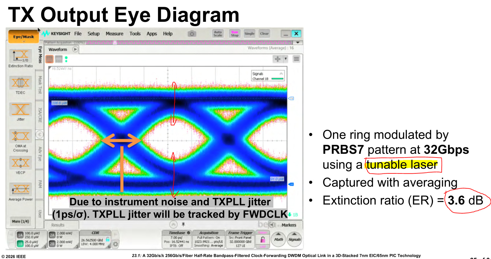
As you can see, the system has very little margin in terms of amplitude noise.
They are using a tunable laser. I can tell which model from the setup diagram.
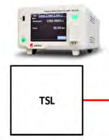
This is a Santec TLS-570 TYPE H, a very popular laboratory-grade laser that almost everyone uses.
They took the picture straight from the datasheet lol.
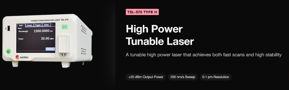
These lasers coast well over $40K and are in critical shortage.
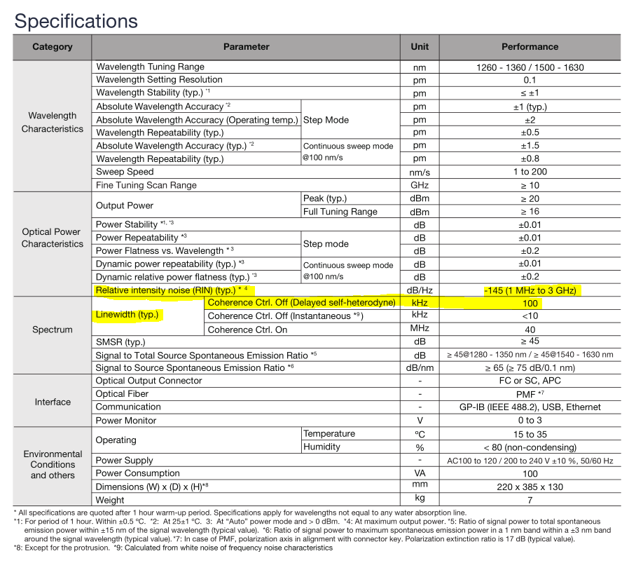
This LABRATORY QUALITY laser has 0.1 MHz linewidth and -145 dBc/Hz RIN.
These are noise specs for the laser.
ONLY LUMENTUM CAN EVEN COME CLOSE TO THESE NOISE SPECS AT THE HIGH POWER (~400 mW CLASS) POWER NEEDED FOR CPO.
Coherent does not have anything.
The margin of these off-resonance ring modulators is so low, Nvidia ABSOLUTLY NEEDS the quality lasers only LITE 0.00%↑ can provide.
[2] Celestial/Marvell
Their results are very good but before that I need to call them out on blatant hypocrisy.
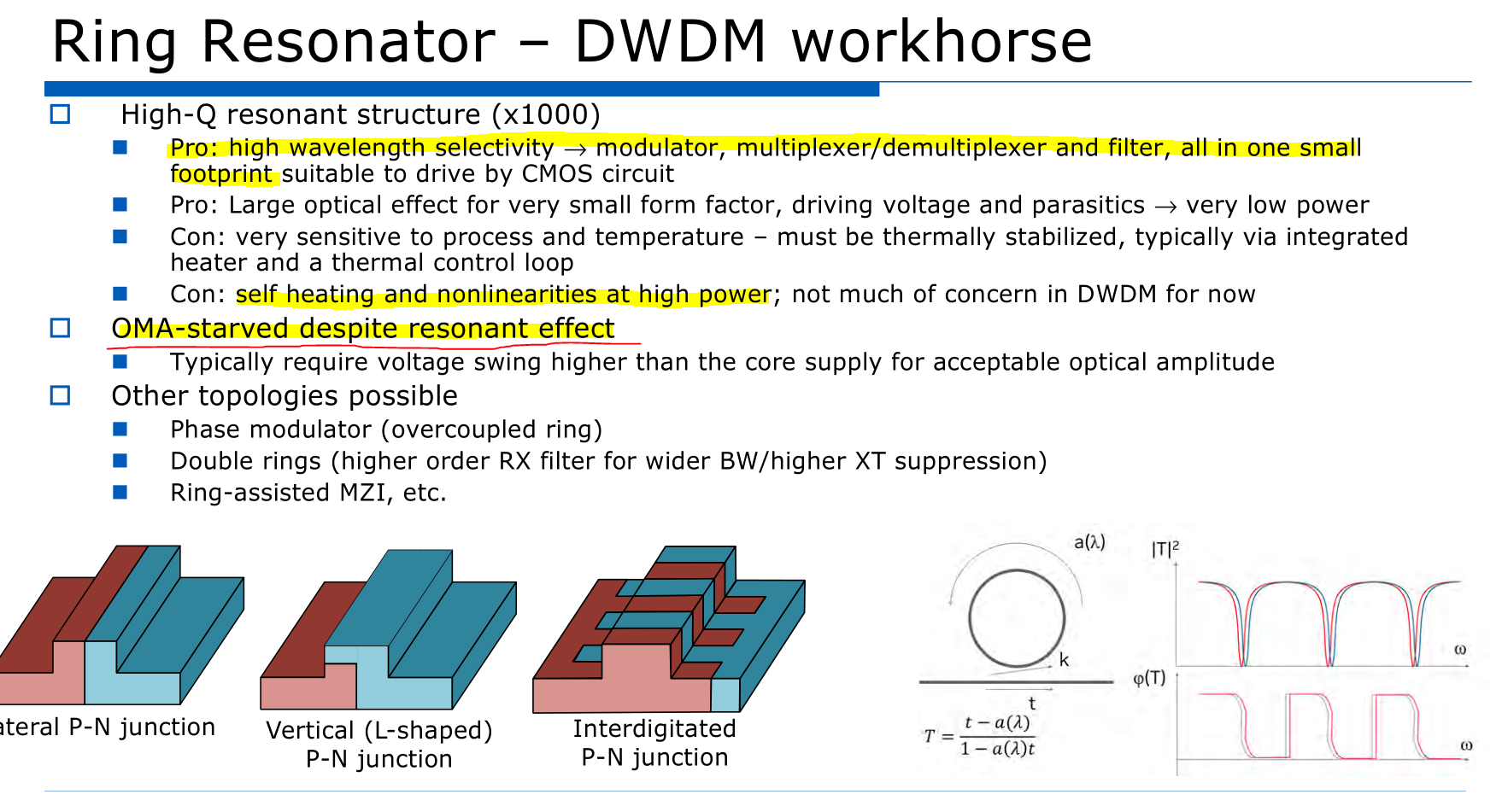
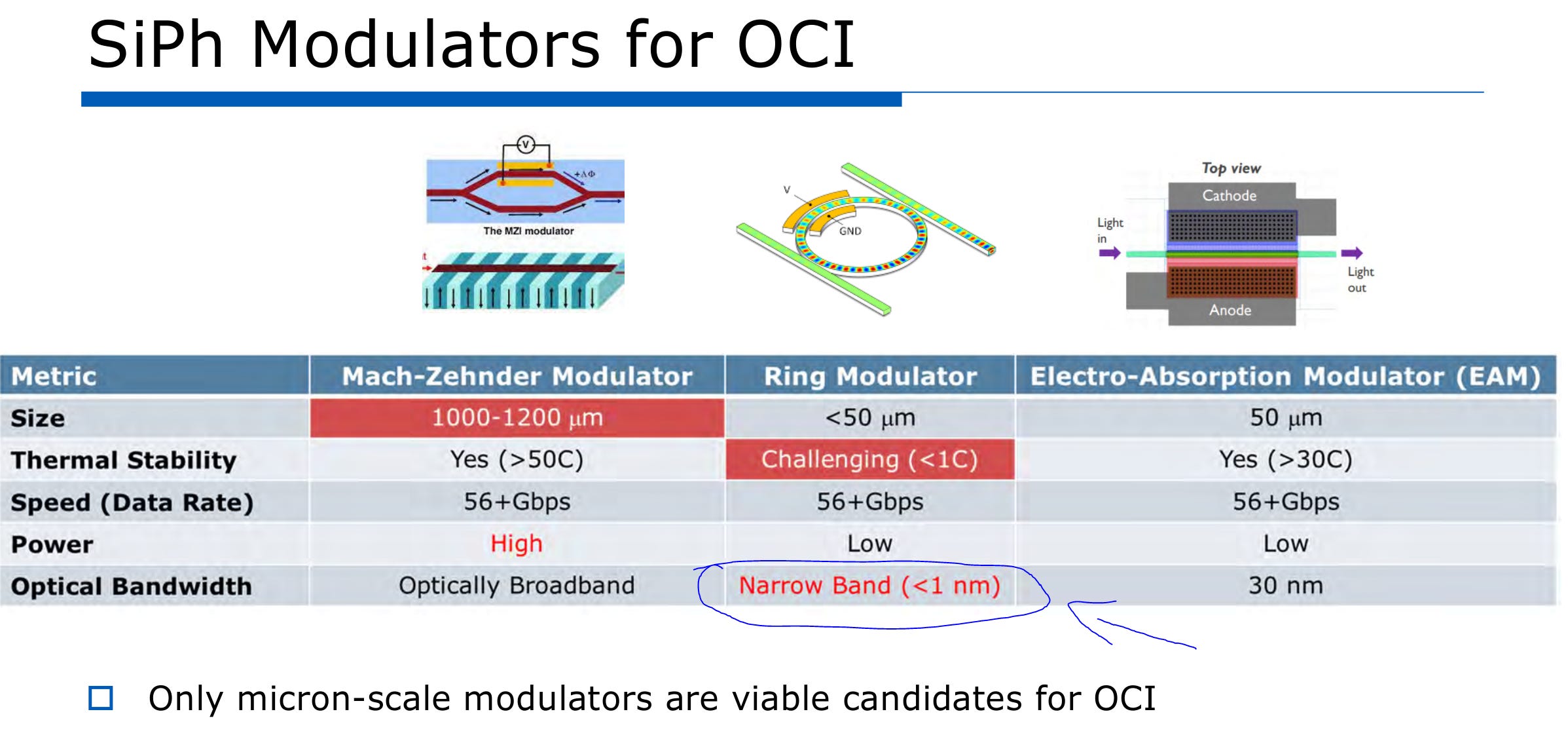
On slide #12, Celestial attacks ring modulators for being narrow-band.
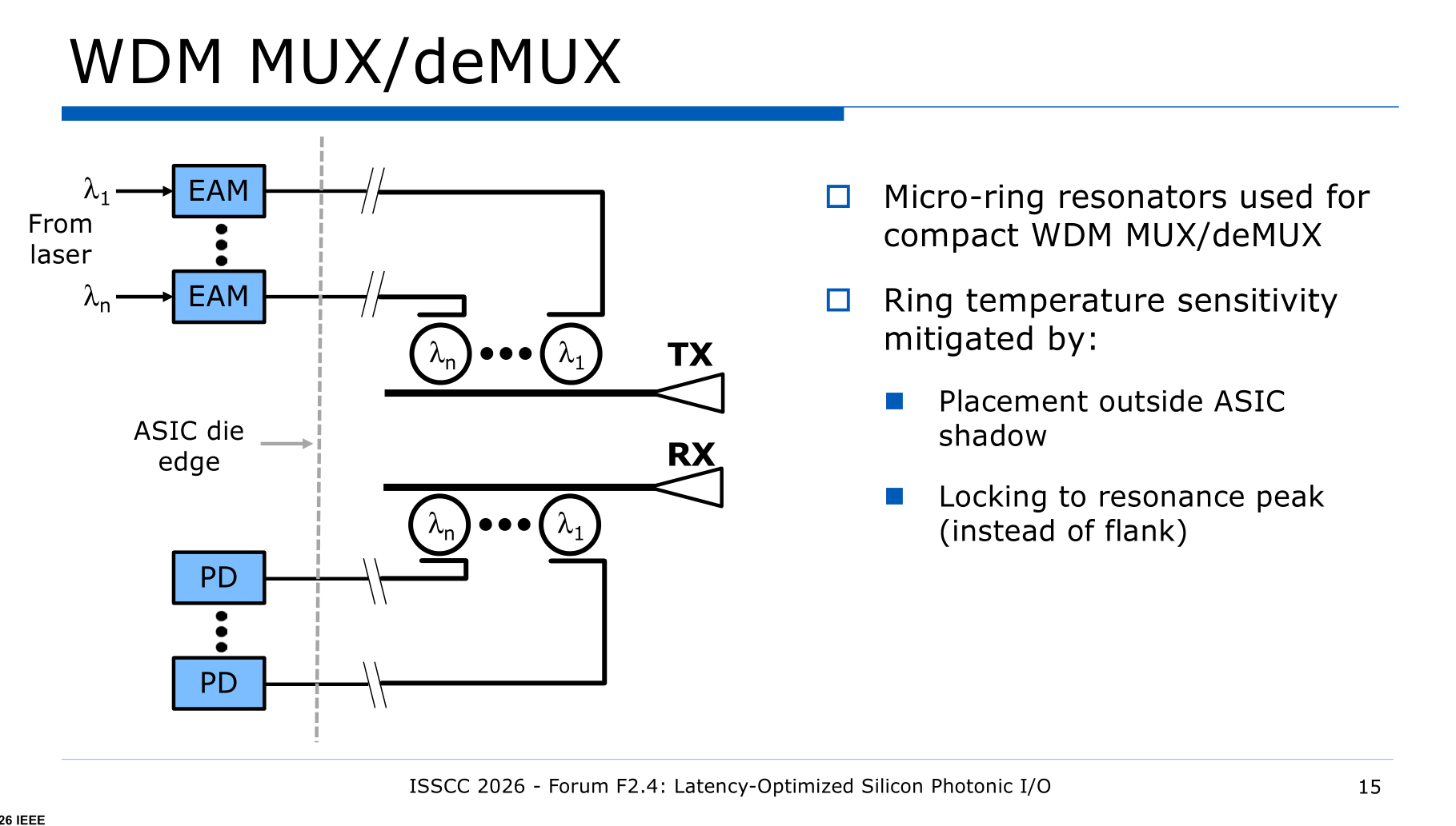
Three slides later, they talk about using ring filters for WDM.
ITS ALMOST AS IF RING MODULATORS ARE BOTH A MODULATOR AND A MUX/FILTER IN A SINGLE STRUCTURE.
Celestial’s own presentation directly contradicts itself.
Also, the claim that ring modulators are “< 50 um” is disingenuous.
Rings are 5 micron. At most 15 micron.
Stop this FUD against rings. You don’t get to criticize rings for being narrow-band while literally implementing ring structures into your system precisely because of the narrow-band effect.
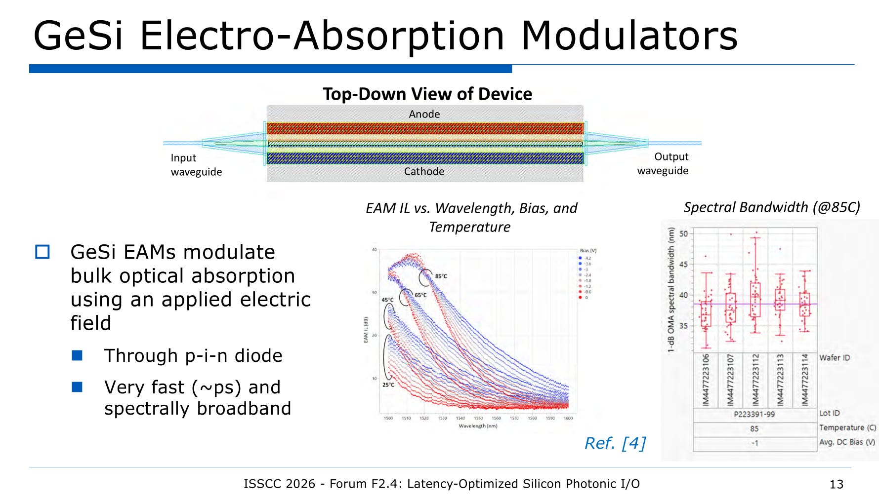
MZI and ring modulators have approximal 5 dB optical insertion loss.
It is well known within industry that EAMs have higher IL. Celestial finally showed their cards.
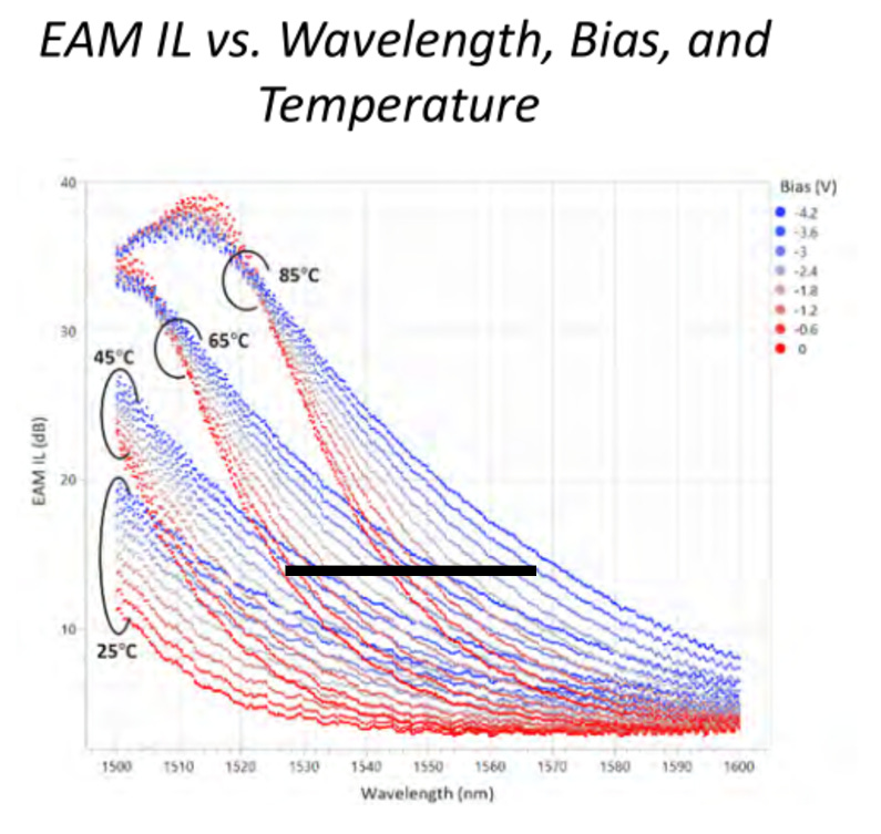
Realistically, the EAMs will run at more than 65C because they will be right underneath the host ASIC.
I think it’s fair to call the typical optical insertion loss of Celestial GeSi EAM at ~15 dB, significantly higher than competing modulators.
This means they have to design a very good receiver and use much more laser power.
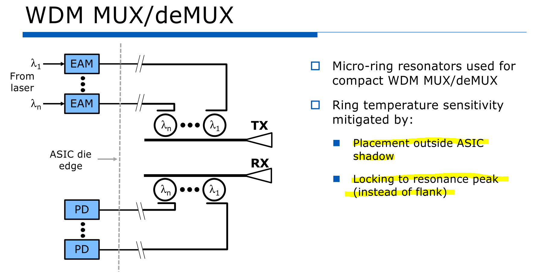
You do realize Nvidia, Ayar Labs, and Lightmatter are all placing their rings outside of ASIC shadow via TSMC COUPE too….?
Locking to resonance peak does not help. In reality, a filter-only ring structure has different metal stackup than a modulating ring. Less thermal resistance. That is why filter rings are easier to control.
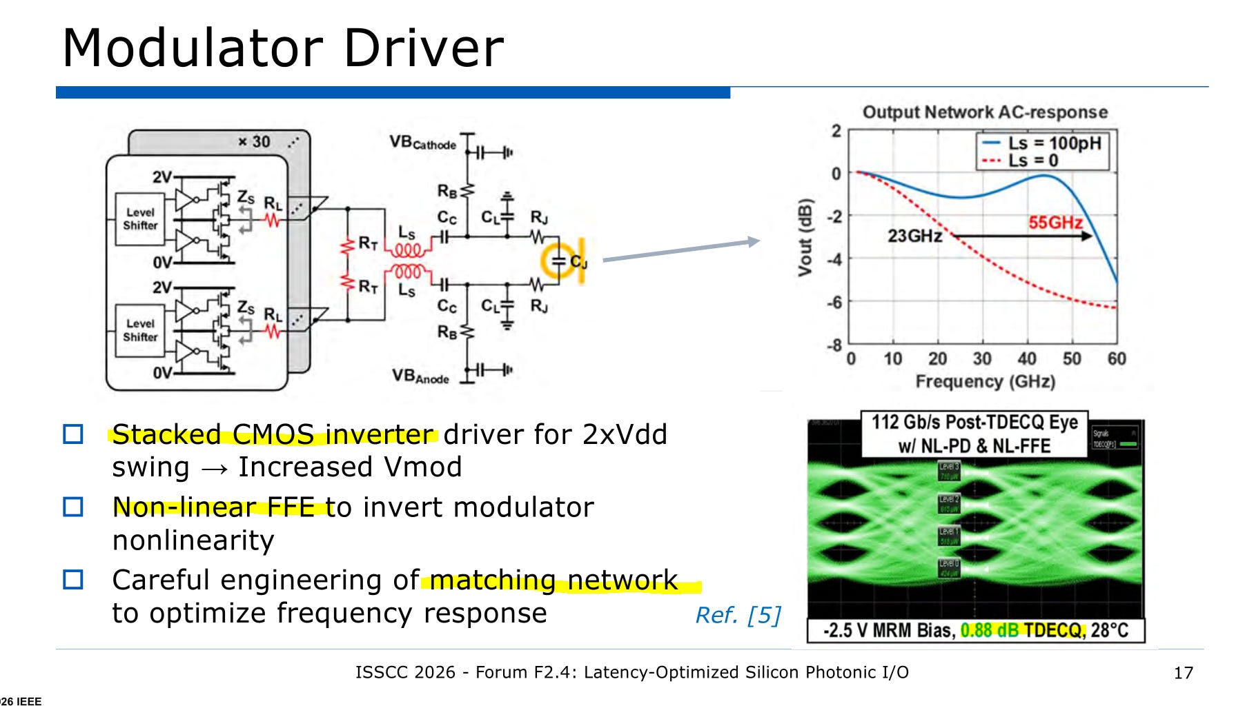
I would call this differential driver instead of stacked.
Non-linear FFE to back-out the modulator transfer function is clever. Difficult to get right due to PVT variations.
Delay matching the differential driver also very difficult. There is a reason most people drive optical modulators single-ended.
The TDECQ result is incredible. Anything less than 1 dB is astounding.
However, there are three possible forms of cheese.
First, the temperature is 28C, quite favorable.
Second, it is unclear if all lanes were active, adding realistic thermal and electrical crosstalk to the lane under measurement.
Finally, it is unclear what TDECQ was used. Standard 112Gbps Ethernet (IEEE 802.3ck) defines TDECQ as having 5 FFE taps. It is possible Celestial modified the math function to have more taps.
Even if all forms of cheese are present, the real (no cheese) TDECQ is certainly under 1.5 dB. Still an excellent result.
In short, these results from Celestial are incredible at best, very good at worst.
This is a problem unique to Celestial and its great they have progress. Unclear how annoying this will be for more complex designs but at least they acknowledge the risk.
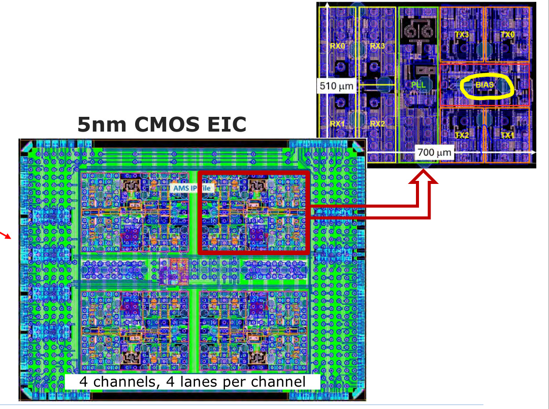
Uh… why is the bias so massive? Strange.
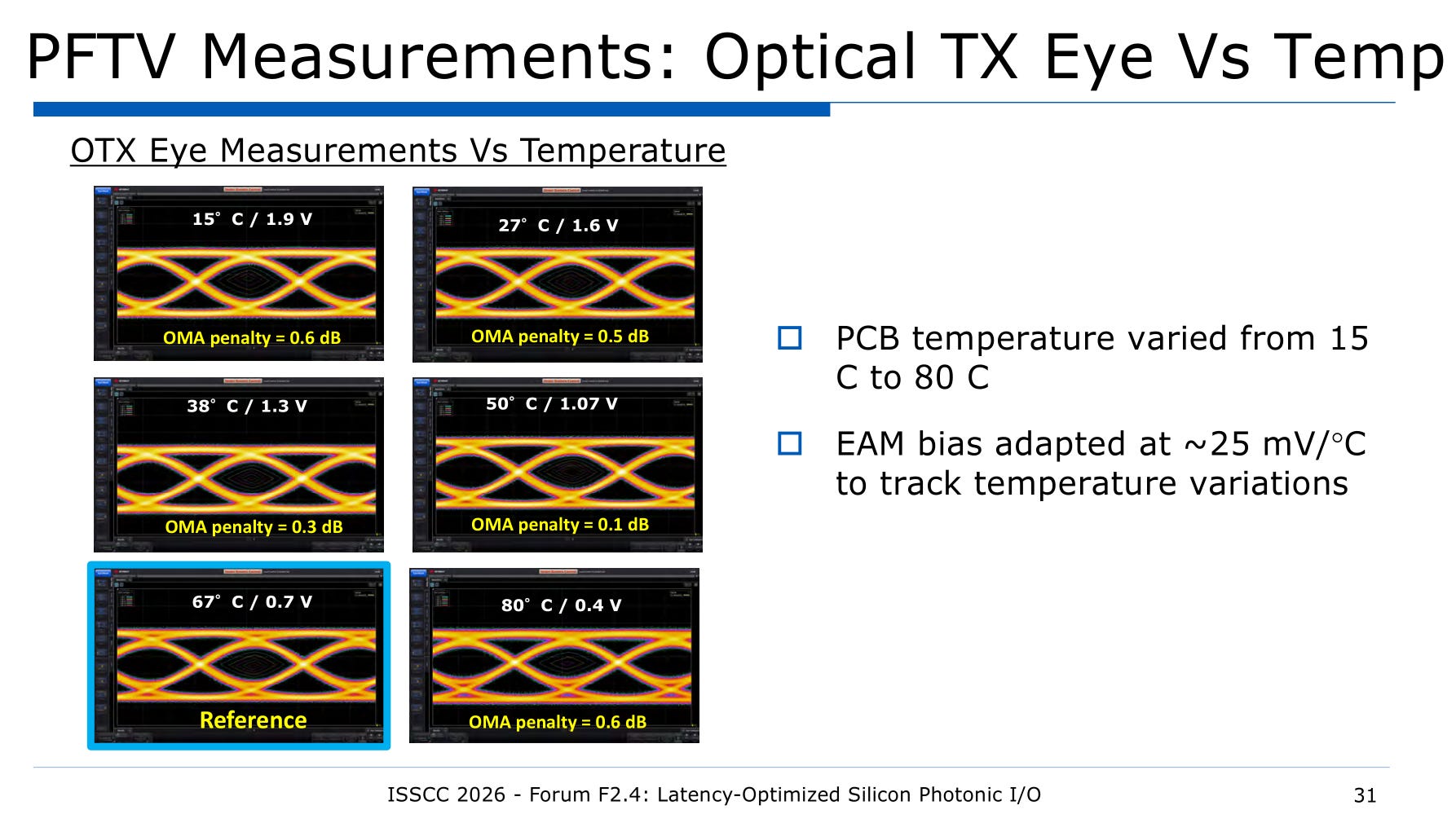
Interesting that 50C is the sweet spot.
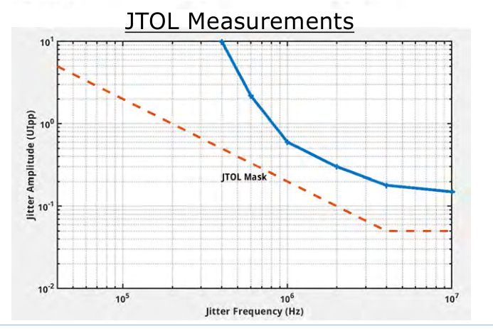
JTOL looks good at first until you take a closer look at x-axis.
They stop at 10 MHz. They should have measured up to 40 MHz.
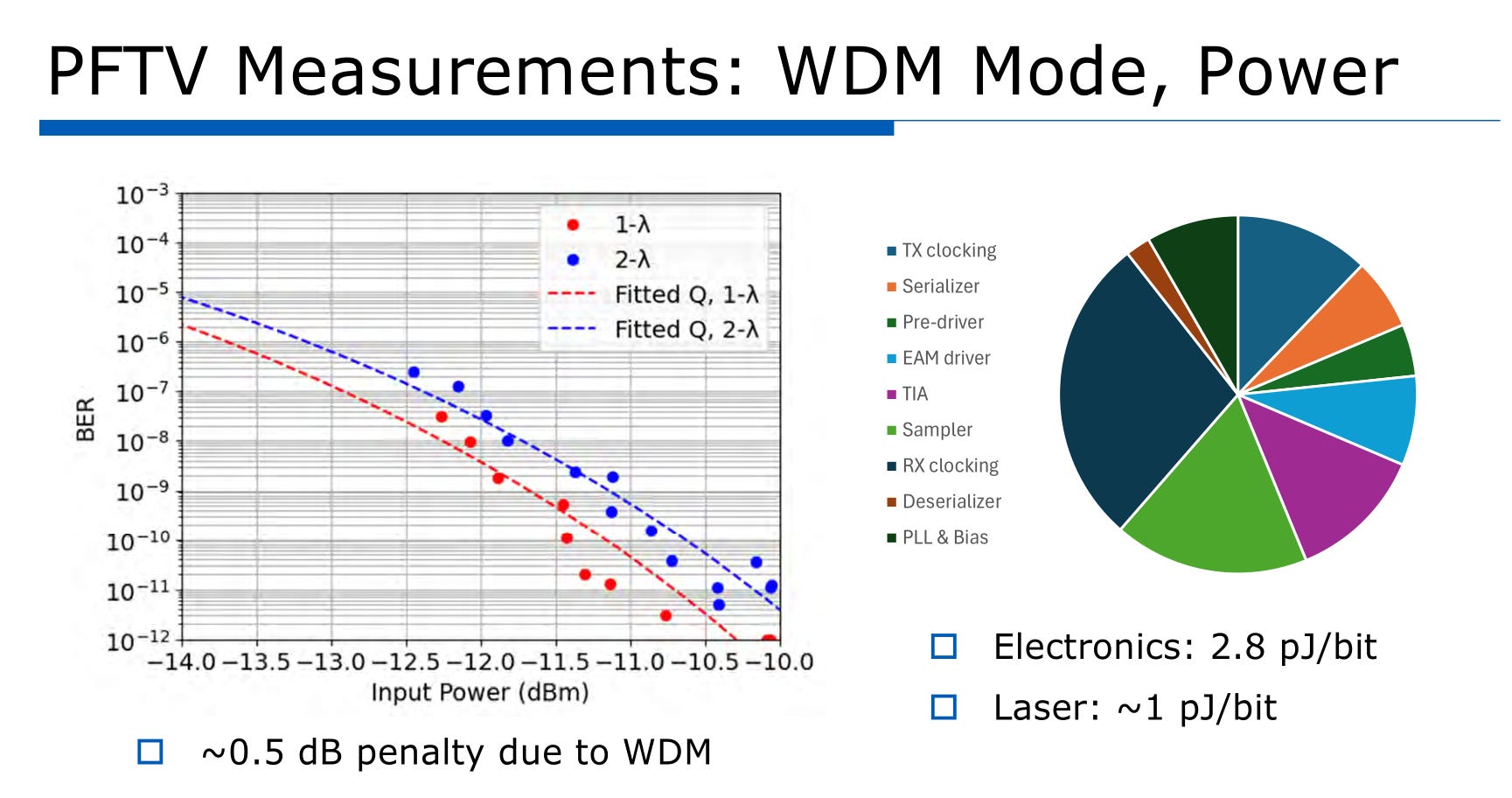
Total energy is 3.8 pj/bit which is pretty good.
Would have liked to see 4-lambda WDM penalty.
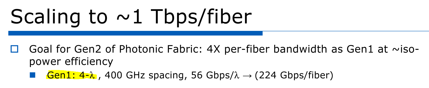
Your gen1 is 4-lambda…
Why no WDM penalty measurement at 4-lambda?
[3] MediaTek
MediaTek mostly presented other people’s work in a “literature review”.
Few parts I want to highlight before trash talk.
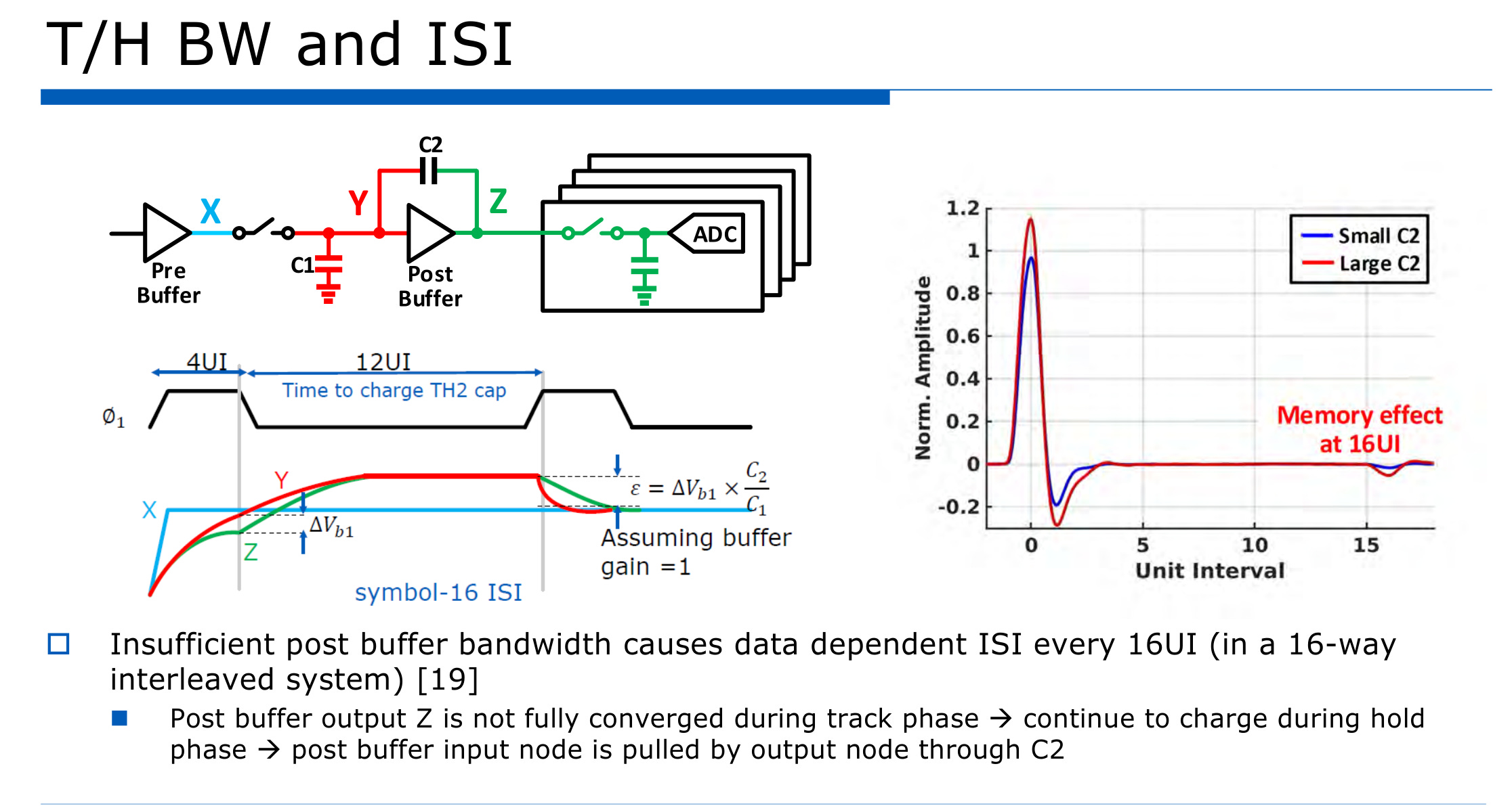
The cited paper [19] is an old Intel paper. What this diagram is showing is gain inside the ADC interleave.
This is a bad idea. It causes nasty guarantied far-field reflections.
In last-years MediaTek 224G N4 SerDes presentation, they took this bad idea from Intel and pushed it way farther. I think this was a mistake. Forced them to use two DFE taps.
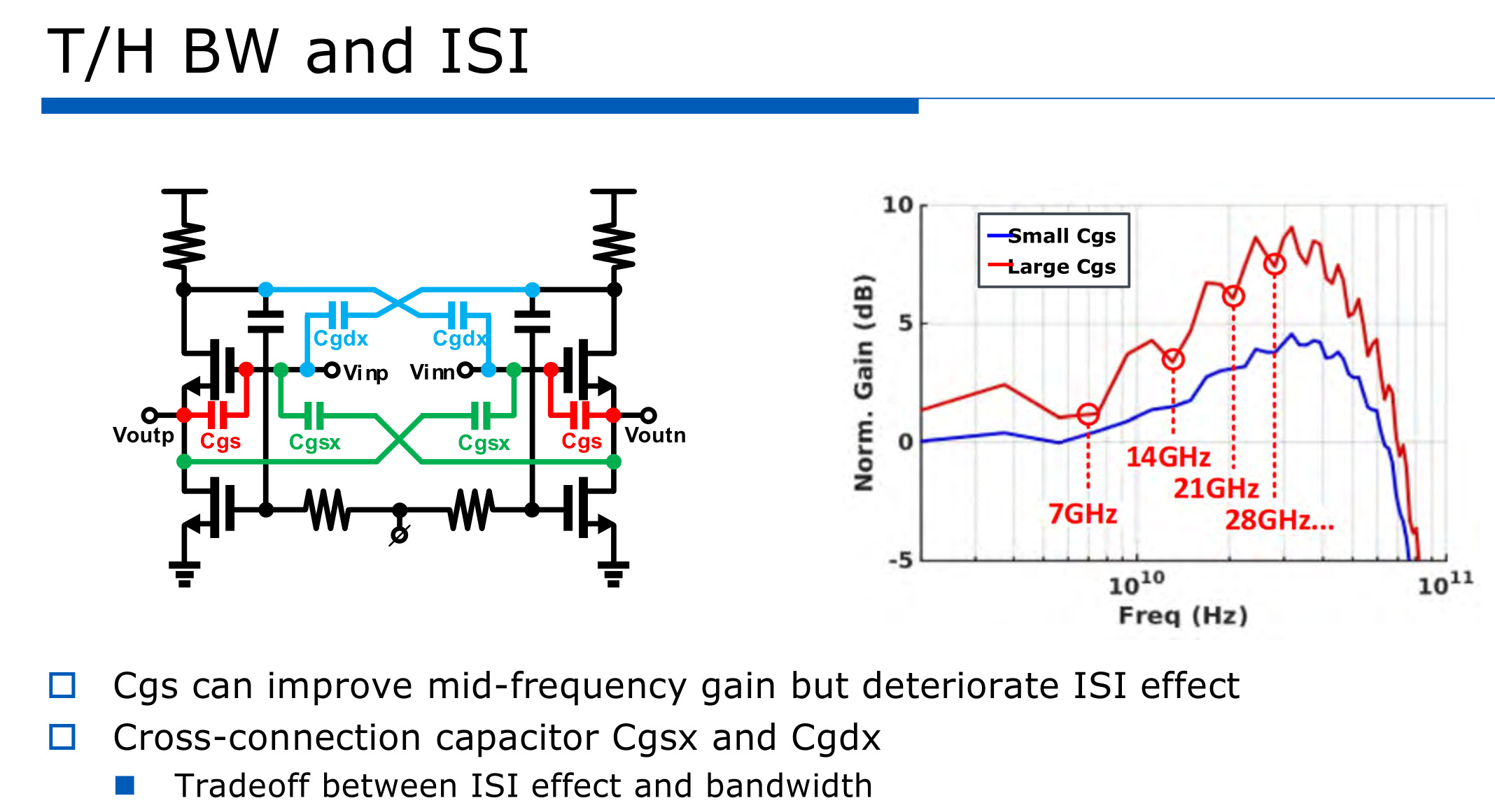
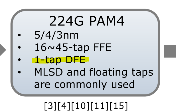
Speaking of those DFE taps…
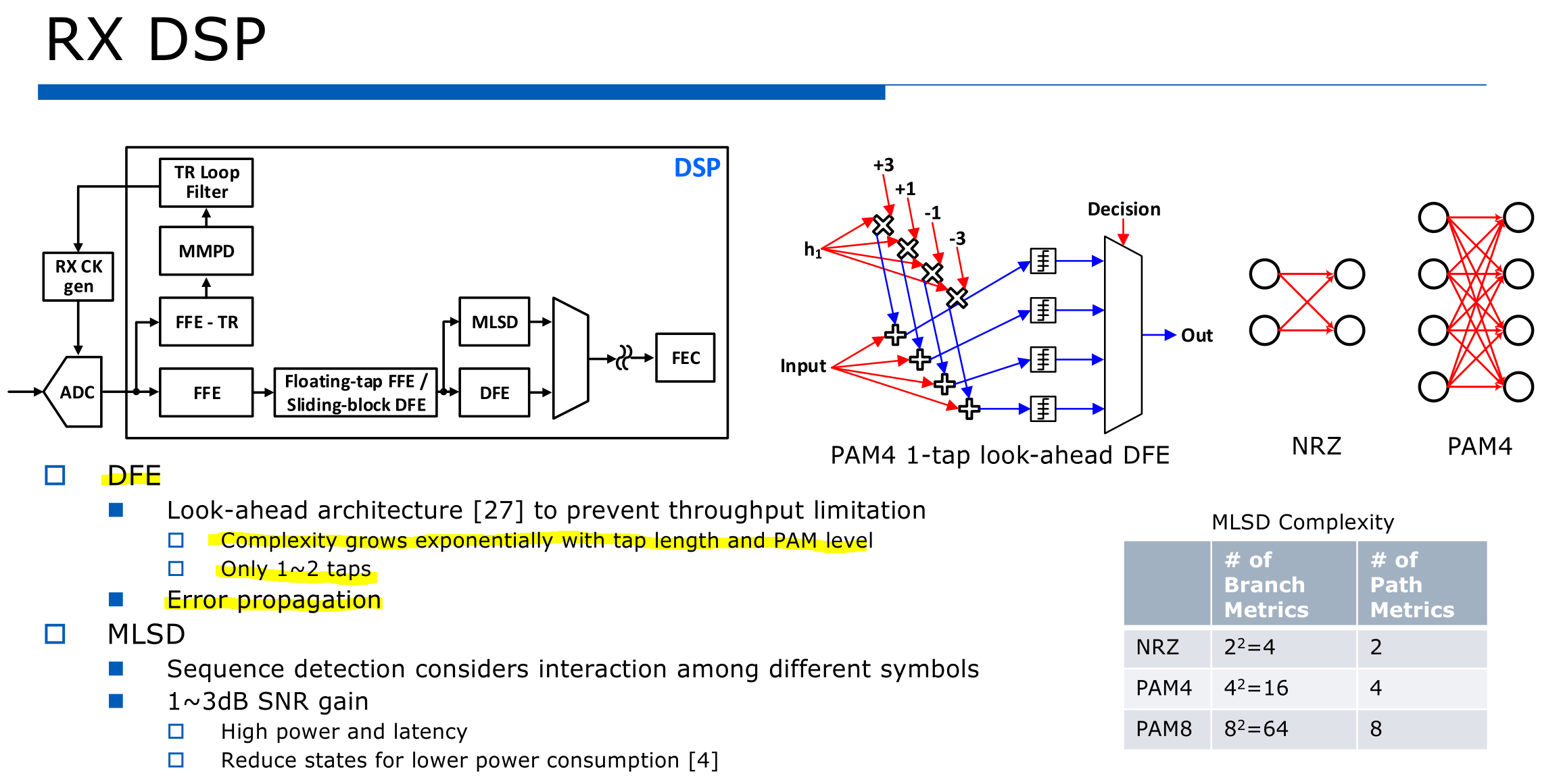
I find it interesting MediaTek acknowledges that only 1-2 DFE tap is viable at high-speed. They seem to be self-aware to an extent.
The limit is 1-tap jokers.
Literally the next slide I see this.
lmao
One of my many little birds tells me a MediaTek employee was massively coping on insertion loss of 224G SerDes.
“40db is very hard, Nvidia even looking at 32. Need to relax to 10-20”
Let me clarify.
Official IEEE 802.3dj spec for 224G Ethernet states that compliance testing shall be done at 40 dB total bump-bump insertion loss.
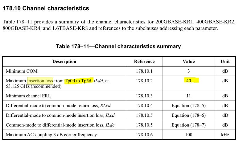
40 dB is the minimum. If the bare minimum is “very hard” then maybe you suck?
Broadcom can easily hit 49 dB as of 18 months ago. They very likely improved since then.
Nvidia scale-up passive copper channels likely 50-55 dB.


[4] Trading Account Update

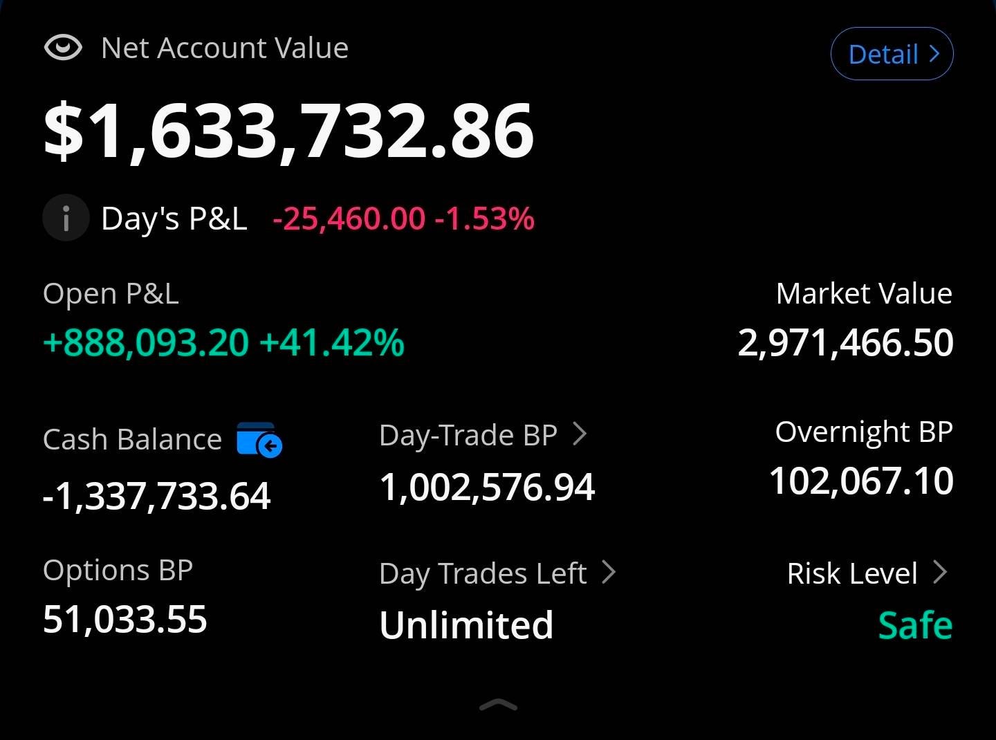
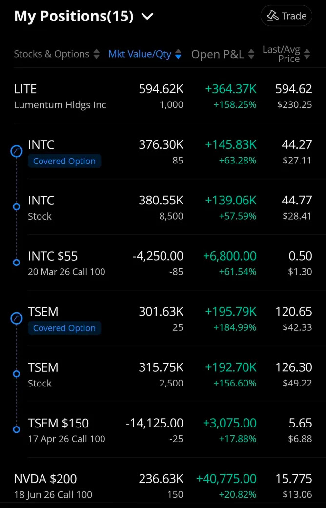
I have a rule against adding to existing position if market value above $200K. Ned to have a very good reason.
Outright self-ban on adding to position above $400K.
It’s the only reason I am not buying more LITE 0.00%↑.
Never go full retard.
He's the Robinhood of sell-side. Free alpha for all. We must protect him at all costs
I understand nothing. Yet this is fabulous! Thank you for the update!